Grid edition
MetaStructure lets you create (and modify) the current structure by defining the nodes, the elements and the restraints in a grid way :
1. Nodes
Select the Nodes tab.
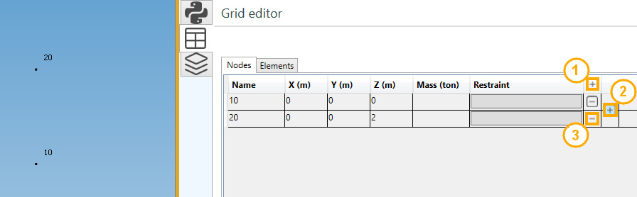
Editing buttons :
- Add a new node
- Insert a new node between 2 existing nodes
- Remove an isolated node (not an extremity of an element)
REM : Place the mouse at the position shown on the upper picture to display the button 2.
1.1 Node properties
| Property | Description | Unit Metric | Unit USA |
|---|---|---|---|
| Name | Text or number, unic (1) | - | - |
| X | X global coordinate | m | ft |
| Y | Y global coordinate | m | ft |
| Z | Z global coordinate | m | ft |
| Mass | Lumped mass | ton | kips |
(1) New node will receive an automatic name based on the Node settings.
Click here for more information about node naming.
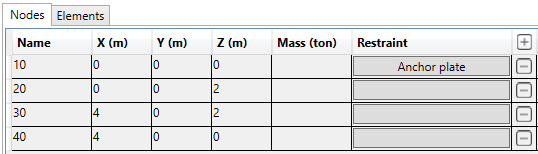
1.2 Restraints
A restraint (anchor or anchor plate) can be defined on node as soon as an element exists on that node.
See §3. for restraint definition.
2. Elements
Select the Elements tab.
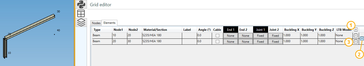
Editing buttons :
- Add a new element
- Insert a new element between 2 existing elements
- Remove an element
REM : Place the mouse at the position shown on the upper picture to display the button 2.
2.1 Add/insert an element
Click on button 1 or 2. A window appears :
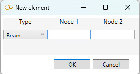
- Select the type : beam, rigid, spring or matrix
- Select the first node name
- Select the last node name
REM : the node names must exist.
2.2 Element properties
| Property | Description | Remark |
|---|---|---|
| Type | beam, rigid, spring or matrix | |
| Node1 | First extremity node name | |
| Node2 | Last extremity node name | |
| Material/Section | Material & section for beams, material for rigid, spring and matrix | |
| Label | Label of the element | |
| Angle | Angle of rotation around element axis | Only for beam |
| Cable | True or false | Only for beam |
| Buckling X | buckling factor in the weak inertia plane | Only for beam |
| Buckling Y | buckling factor in the strong inertia plane | Only for beam |
| Buckling Z | the lateral-torsional buckling factor | Only for beam |
| LTB Model | Lateral-Torsional Buckling model | Only for beam |
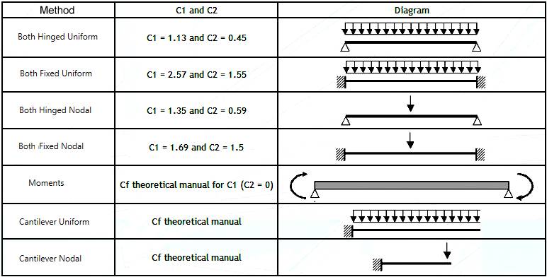
The Lateral-Torsional Buckling model (LTB) must be defined for the calculation of the elastic critical moment according to Eurocode 3.
This critical moment depends on the coefficients C1 and C2 :
2.3 Graphical ending
The extremities of a selected beam can be mofified.
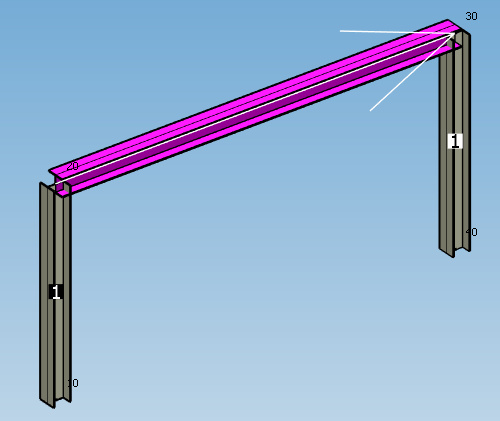
The beams connected to the first extremity are numbered in a black square.
The beams connected to the last extremity are numbered in a white square.
Click on the button of the correct extremity (black or white column) to modify the graphical ending :
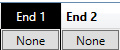
Set the properties of the selected ending :
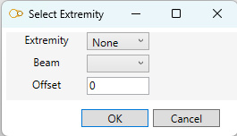
The extremity can be :
- None
- Front
- Back
- Miter
Click here for more information about graphical ending.
2.4 Joint
The joints of a selected beam can be mofified.
The beams connected to the first extremity are numbered in a black square.
The beams connected to the last extremity are numbered in a white square.
Click on the button of the correct extremity (black or white column) to modify the joint :
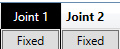
Choose a joint type :
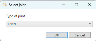
| Type | Description |
|---|---|
| Fixed | Rigid joint (transmission of moments) |
| Detailed | User can specify the 3 translation stiffnesses and 3 rotation stiffnesses |
| Bolted | User can define a bolted joint |
| Welded | User can define a welded joint |
Click here for more information about beam joints.
3. Restraints
Select the Nodes tab.
Click on the restraint button on the desired node :
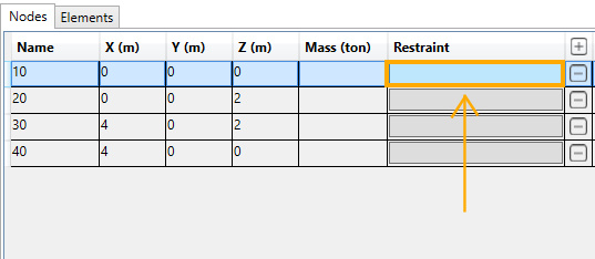
REM : an element must exists at that node.
The restraint edition panel opens :
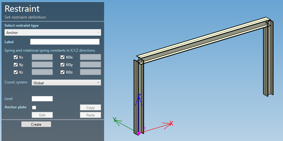
Click here for more information about restraint definition.
After the definition of a restraint on node, the button appears with a title (Anchor plate in this example) :