Create pipes
1. New project
Select a specification (default = Out of spec) and a current section.
Click on the Draw piping button.
As we start the modeling, we need to create a First node :
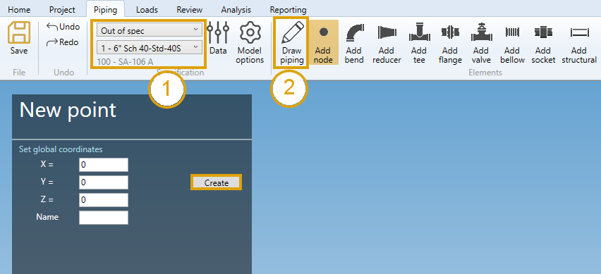
Click here for more information about the First node creation.
1.2. Draw the first pipe
After the first node has been created, you can draw your first pipe :
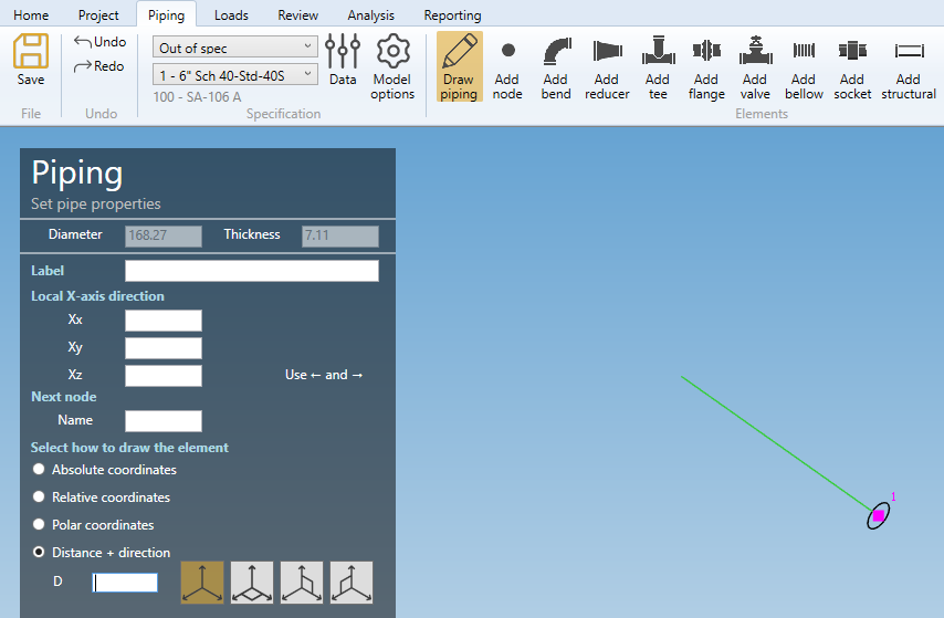
The Diameter and Thickness properties come from the current specification.
To know the UNIT of the value, just let the mouse over the cell.
LABEL :
You can define a label to this element. The labels are shown with the node names view button.

X-AXIS DIRECTION :
You can define the X-axis vector by defining Xx, Xy, Xz in global coordinates.
Use the left and right keyboard arrows to turn the X-axis vector 90°/-90°around the tangent direction.
NEXT NODE :
You can set the next extremity node name of the element. If blank, the software will define it automatically. The software will also check that the name doesn’t already exist.
The only thing you have to do is to select how to draw the pipe.
Click here for more information about the orientation tool.
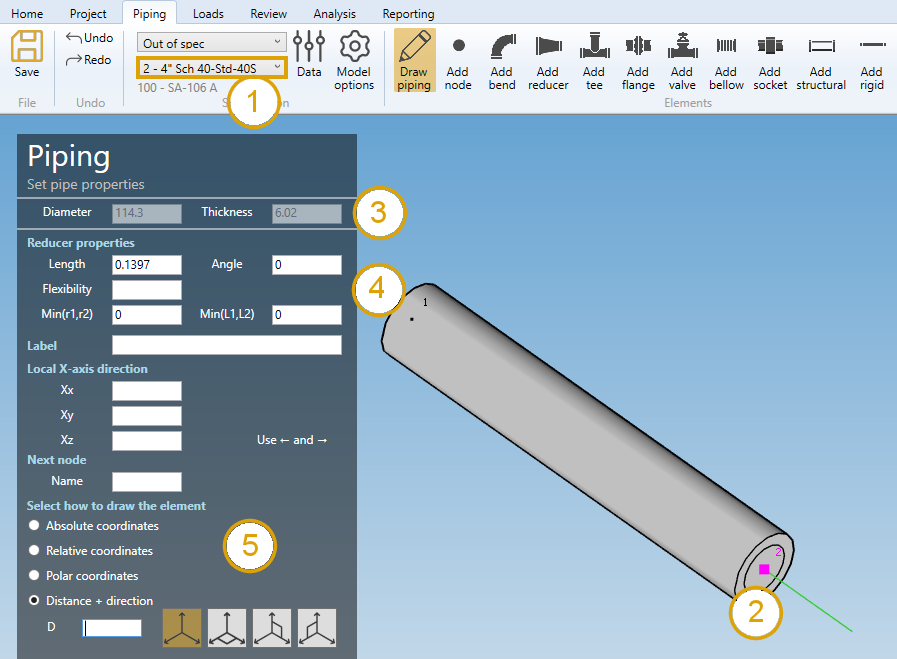
2. Draw piping
When you click on the Draw piping button without selection, the left panel shows a message :
Select a node
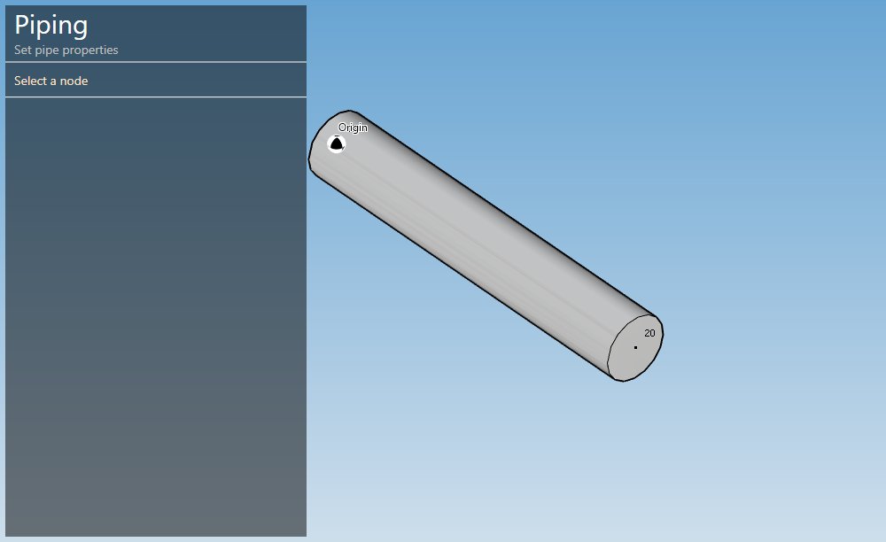
The selection mode is automatically set to POINT. You can so directly select a node :
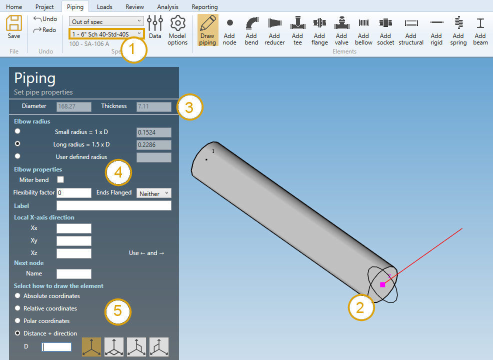
- Select the current section/material in the specification box.
- Select a node.
- The current diameter and thickness is shown on top of the left panel.
Click here for more information about the selection tool.
MetaPiping checks the section of the element on the selected node.
2.1 Same section
If the section of the element on the selected node is the same as the current section (1), the left panel shows ELBOW PROPERTIES (4).
Click here for more information about the elbow properties.
You can then define the second point of the pipe thanks to the Orientation tool (5).
Click here for more information about the orientation tool.
Based on the elbow properties and the second point definition (distance D in X direction for example), the pipe is created with a bend :
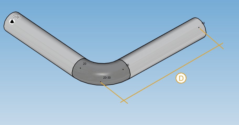
The distance D start from old point 20 to point 40. An elbow is then inserted from new point 20 - point 20-30 to point 30.
The previous pipe is reduced from old point 20 (actually point 20-30) to new point 20.
You can undo this command.
2.2 Different section
If the section of the element on the selected node is different from the current section (1), the left panel shows REDUCER PROPERTIES (4).
ATTENTION, you are supposed to draw the pipe tangent from the previous one.
Click here for more information about the reducer properties.
You can then define the second point of the pipe thanks to the Orientation tool (5).
Click here for more information about the orientation tool.
Based on the reducer properties and the second point definition (distance D in TANGENT direction for example), the pipe is created with a reducer :
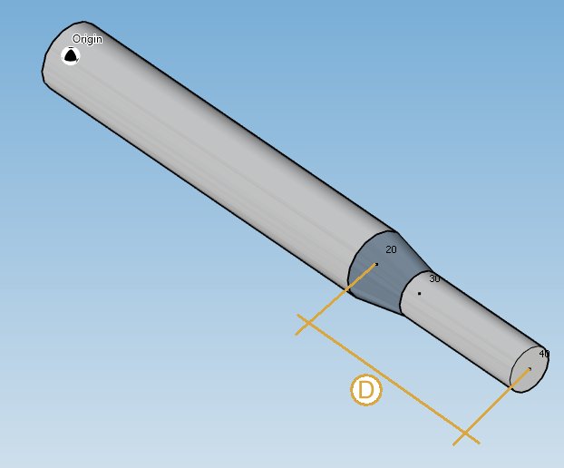
The previous pipe is NOT affected.
You can undo this command.
Remark : you can also draw a pipe from one node to another node. Just by clicking on the target node.
3. Modify/Remove a pipe
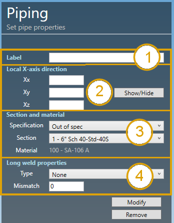
Change the Selection mode to ELEMENT and select a pipe :
Click here for more information about the selection tool.
LABEL (1) :
You can define a label to this element. The labels are shown with the label view button.
X-AXIS DIRECTION (2) :
You can change the X-axis vector by defining Xx, Xy, Xz in global coordinates.
SECTION AND MATERIAL (3) :
You can change the specification and section/material of the pipe.
LONG WELD (4) :
You can change the Long weld properties :
For the type, you can choose between :
- None
- Butt weld flush
- Butt weld as welded
Based on this property, define the Long weld mismatch [mm or in].
Click on the Modify button to change the selected pipe with these new properties.
You can undo this command.
Click on the Remove button to delete the selected pipe.
You can undo this command.
COMPOSITE PIPE :
If the material of the pipe is Composite, a special property Glue appears :
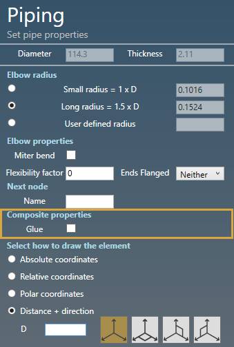
This property indicates that the pipe is a connectivity element.