Create flanges
When you click on the Add flange button without selection, the left panel shows a message :
Select 1 node
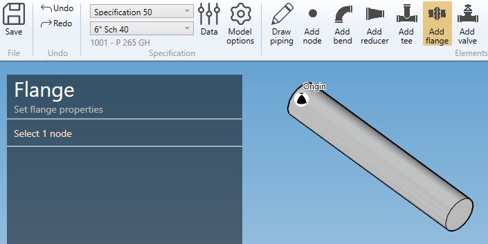
The selection mode is automatically set to POINT. You can so directly select a node.
1. Create a flange
- Select the current section/material in the specification box.
- Select a node.
- Click the Add flange button.
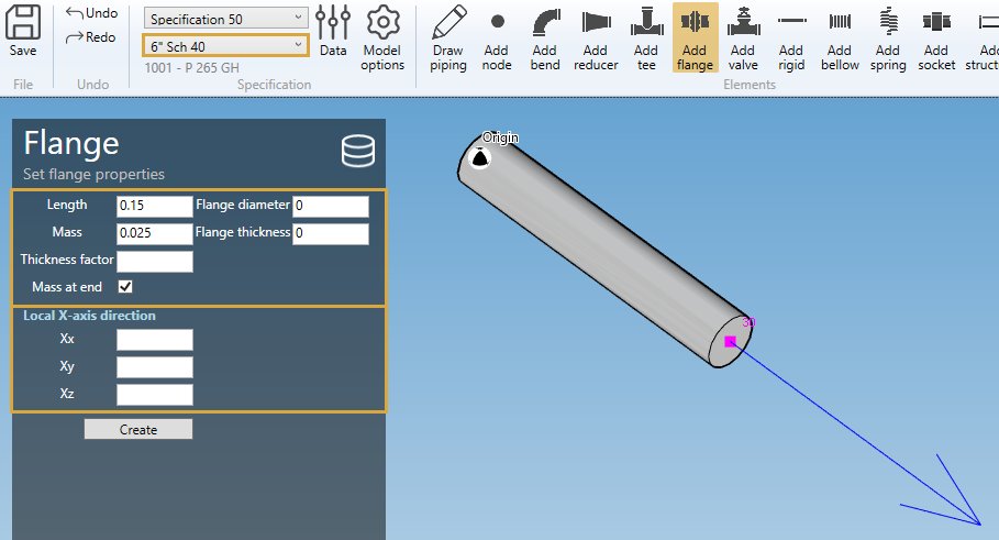
By default, the orientation of the element is defined to Insert represented by a blue arrow with direction tangent to the previous element.
You can decide to use the orientation tool to define another direction by unchecking this option. This panel will appear :
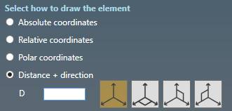
Click here for more information about the orientation tool.
FLANGE PROPERTIES :
Define the properties of the new flange :
| Property | Unit Metric | Unit USA |
|---|---|---|
| Length | m | ft |
| Mass | ton | kips |
| Thickness factor | - | - |
| Diameter of the flange | mm | in |
| Thickness of the flange | mm | in |
| Mass at end | - | - |
The wall thickness is increased by the thickness factor by equally increasing the outer diameter and decreasing the inner diameter, keeping the mean diameter the same as that of connected pipe. The thickness value is reduced if the wall thickness is too great. Default = 3.
The Length and Mass come from the current specification :
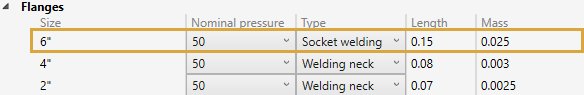
To save time, you can also directly select a flange from database :
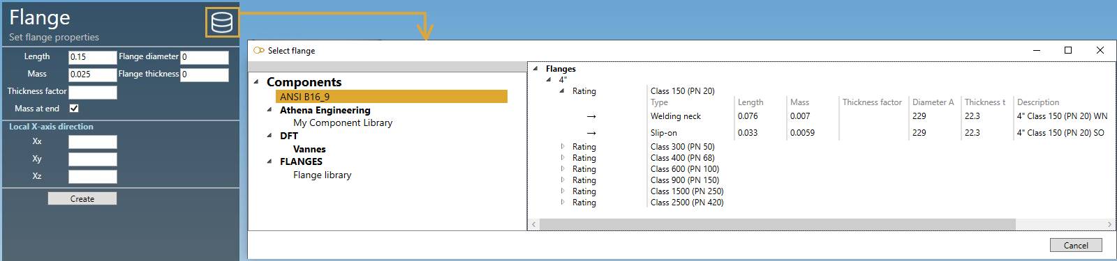
Click on the Database button, select a Library and a Flange. The OK button will appear.
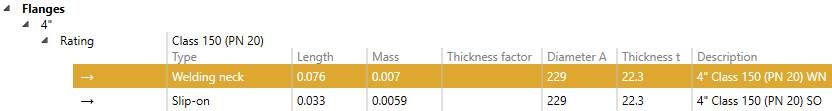
The Rating and the Type is just informative.
The tables will be filled automatically :
Click here for more information about creation of library of components.
X-AXIS DIRECTION :
You can define the X-axis vector by defining Xx, Xy, Xz in global coordinates.
Use the left and right keyboard arrows to turn the X-axis vector 90°/-90°around the tangent direction.
LABEL :
You can define a label to this element. The labels are shown with the node names view button.

NEXT NODE :
You can set the next extremity node name of the element. If blank, the software will define it automatically. The software will also check that the name doesn’t already exist.
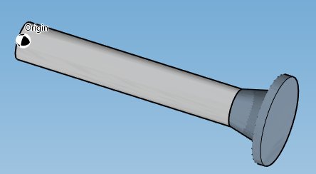
Click on the Create button to create the flange.
You can undo this command.
2. Modify/Remove a flange
Change the Selection mode to ELEMENT and select a flange :
Click here for more information about the selection tool.
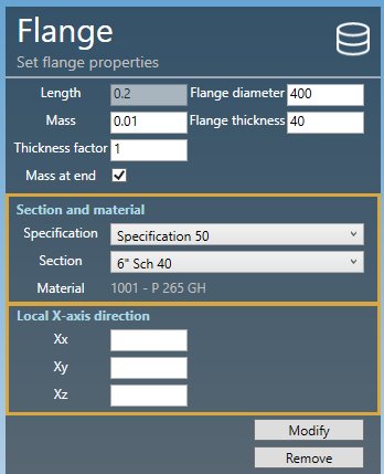
You can change the properties of the selected flange (except the length).
SECTION AND MATERIAL :
You can change the specification and section/material of the flange.
X-AXIS DIRECTION :
You can change the X-axis vector by defining Xx, Xy, Xz in global coordinates.
LABEL :
You can modify the label of the valve. The labels are shown with the node names view button.
Click on the Modify button to change the selected flange with these new properties.
You can undo this command.
Click on the Remove button to delete the selected flange.
You can undo this command.
3. Insert a flange on an intermediate node
Click on the Add flange button and select an intermediate node between 2 elements.
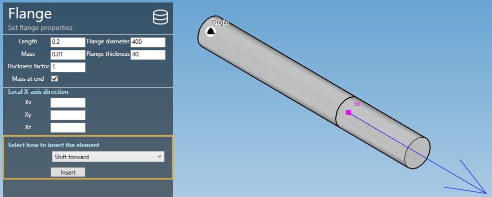
Fill the properties (see §1) and select the insertion mode :
- Shift forward
- Shift backwards
- Reduce the next element
- Reduce the previous element
- Symmetrically reduce the neighboring elements
ATTENTION, if the length is null, no mode will be proposed (empty list)
Based on the length of the flange and the lengths of the neighboring elements, some mode could be hidden.
Select for example “Symmetrically reduce the neighboring elements” and click the Insert button :
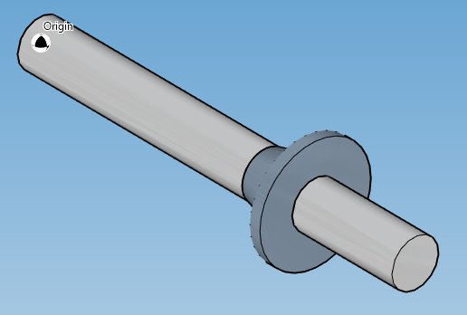
You can undo this command.