Sample 12 : Create a beam support of a piping on a node
1. Goal
Create a script that will (after selecting a piping node with a restraint and pressing a button in the ribbon) show a window with variables and build several beams like in this picture :
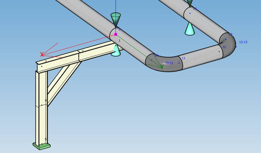
Since the user will have to create a COMMAND, the application will manage the undo/redo operations by itself !
2. Script definition
From the Home/Python, click on button 2 (Add script) :
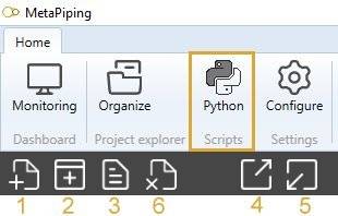
Select “Design script” and give it the name “Support1”
Say NO to the question about creation of virtual environment. The Requirements.txt will be hidden.
3. Script files
This kind of script needs some images in order to illustrate the button and the window.
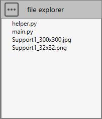
Press the “three points” button and select “Import image”. You need to create a 32x32 transparent PNG for the icon of the button and an illustration of the support for the window.
Press the “three points” button and select “Add a python file”. We will create a file for some helper functions.
3.1 helper.py
Select the file.
Copy/paste this code in the Editor :
##########################
# Model helper functions #
##########################

from Cwantic.MetaPiping.Core import BeamExtremity, LTBModel

# Method that check if a node contains a restraint
def getRestraint(node, model):
    for restraint in model.Restraints:
        if restraint.Node == node:
            return restraint
    return None

# Method that return the first pipe on node
def getFirstPipe(design, node):
    for element in node.Elements:
        if design.isType(element, "Pipe"):
            return element
    return None

# Initialize a new CurrentValues for beam
def initializeCurrentValues(currentValues):
    other = currentValues.Clone()
    other.BeamIndexExtremity1 = 0
    other.BeamIndexExtremity2 = 0
    other.BeamOffset1 = 0
    other.BeamOffset2 = 0
    other.BeamJoint1 = None
    other.BeamJoint2 = None
    other.BeamLTBModel = LTBModel.BothHingedUniform
    other.BeamExtremity1 = BeamExtremity(0)    # Tip : cannot set BeamExtremity.None so use 0 instead
    other.BeamExtremity2 = BeamExtremity(0)    # Tip : cannot set BeamExtremity.None so use 0 instead
    other.CheckModel = False
    return other
Save it !
4. Script properties
In this kind of script, user has to define the button :
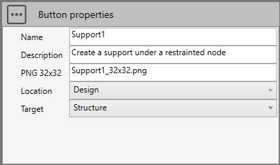
The Target is Structure!
The location will be Design so that the button appears on the right tab with its icon and description.
5. main.py
Select the file.
Copy/paste this code in the Editor :
###################################
# Create support on selected node #
###################################

import os
from System.Windows.Media.Media3D import Vector3D
from System.Collections.Generic import List
from helper import getRestraint, getFirstPipe, initializeCurrentValues
from Cwantic.MetaPiping.Core import Node, Element, AddNodeCommand, AddBeamCommand, MassModel, BeamExtremity, CoordinateSystem

# Default error message
message = "Select a node with restraint !"

# Inspect selection
n = len(design.selectedList)
if n==1:
    # Check the type of selected element
    if design.isType(design.selectedList[0], "Node"):
        node = design.selectedList[0]

        # Get the current metal
        model = design.getMetal()

        # Get the metal of the node (can be a LINKED metal so do not use getMetal)
        selectedModel = design.getMetalWithSelection(node)

        # Get the script directory
        directory = design.getScriptDirectory()

        # Check if a restraint exists on this node
        restraint = getRestraint(node, selectedModel)
        if restraint != None:
            # Get the first pipe on node
            pipe = getFirstPipe(design, node)
            if pipe != None:
                # Get the pipe ray
                ray = pipe.Section.Diameter / 2
                # Get the pipe direction
                pipevec = Vector3D(pipe.DL.X, pipe.DL.Y, pipe.DL.Z)
                pipevec.Normalize()
                # Get the model vertical vector (+Z or +Y)
                verticalvec = design.getVerticalVector()
                # Get the horizontal vector perpendicular to pipe
                horizontalvec = Vector3D.CrossProduct(pipevec, verticalvec)
                horizontalvec.Normalize()

                # Get the current beam default values (section, material, extremities,...)
                currentValues = design.getCurrentSpecValues()

                # Add the half distance of the current beam section to ray
                dist = ray + currentValues.MKS_SpecBeamSection.H / 2

                # Get node altitude
                if verticalvec.Y == 1:
                    altitude = node.Coor.Y
                else:
                    altitude = node.Coor.Z

                # Initialize offset and anchor
                offset = 0
                anchor = True

                # Get variable values - create a window
                window = design.createVariableWindow()
                window.AddComment("Fill the variables and click on OK. The support will be perpendicular to the pipe and tangent. L can be positive or negative. [meter]")
                window.AddValue("L", "L =", 2)
                window.AddValue("H", "H =", altitude)
                window.AddValue("DL", "L1 =", 1)
                window.AddValue("DH", "H1 =", 0.5)
                window.AddList("OFFSET", "Offset =", ["No offset", "Pipe ray", "0.5 m"], 1)
                window.AddCheck("ANCHOR", "Anchor =", anchor)
                window.AddImage(os.path.join(directory, "Support1_300x300.jpg"))
                if window.ShowModal():
                    L = window.GetValue("L")
                    H = window.GetValue("H")
                    DL = window.GetValue("DL") * L / abs(L)
                    DH = window.GetValue("DH")
                    OFFSET_ID = window.GetValue("OFFSET")
                    if OFFSET_ID == 1:
                        offset = ray
                    else:
                        if OFFSET_ID == 2:
                            offset = 0.5
                    ANCHOR_ID = window.GetValue("ANCHOR")
                    anchor = ANCHOR_ID == 1

                    # Create a new USER command : cmd
                    cmd = design.createCommand("AddSupport1")

                    # Create nodes - we need temporary commands to get new nodes (1 to 5) to pass to node, beam and anchor commands
                    node1Cmd = AddNodeCommand(model, node.Coor.X - dist*verticalvec.X, node.Coor.Y - dist*verticalvec.Y, node.Coor.Z - dist*verticalvec.Z, "", False, currentValues)
                    node1 = node1Cmd.Node

                    node2Cmd = AddNodeCommand(model, node1.Coor.X + (L-DL)*horizontalvec.X, node1.Coor.Y + (L-DL)*horizontalvec.Y, node1.Coor.Z + (L-DL)*horizontalvec.Z, "", False, currentValues)
                    node2 = node2Cmd.Node

                    node3Cmd = AddNodeCommand(model, node1.Coor.X + L*horizontalvec.X, node1.Coor.Y + L*horizontalvec.Y, node1.Coor.Z + L*horizontalvec.Z, "", False, currentValues)
                    node3 = node3Cmd.Node

                    node4Cmd = AddNodeCommand(model, node3.Coor.X - DH*verticalvec.X, node3.Coor.Y - DH*verticalvec.Y, node3.Coor.Z - DH*verticalvec.Z, "", False, currentValues)
                    node4 = node4Cmd.Node

                    node5Cmd = AddNodeCommand(model, node3.Coor.X - H*verticalvec.X, node3.Coor.Y - H*verticalvec.Y, node3.Coor.Z - H*verticalvec.Z, "", False, currentValues)
                    node5 = node5Cmd.Node

                    # Create node sub commands
                    cmd.addSubCommand("AddNodeCommand", [node1, -1])
                    cmd.addSubCommand("AddNodeCommand", [node2, -1])
                    cmd.addSubCommand("AddNodeCommand", [node3, -1])
                    cmd.addSubCommand("AddNodeCommand", [node4, -1])
                    cmd.addSubCommand("AddNodeCommand", [node5, -1])

                    # Create beam sub commands
                    # Tip : each command must have its own currentValues, initializeCurrentValues create a clone and initialize values
                    currentValues = initializeCurrentValues(currentValues)
                    currentValues.BeamOffset1 = offset
                    cmd.addSubCommand("AddBeamCommand", [node1, node2, node2.Coor.X-node1.Coor.X, node2.Coor.Y-node1.Coor.Y, node2.Coor.Z-node1.Coor.Z, MassModel.HalfAtBoth, 0.0, verticalvec.X, verticalvec.Y, verticalvec.Z, currentValues, -1])

                    currentValues = initializeCurrentValues(currentValues)
                    beamCmd = AddBeamCommand(model, node2, node3, node3.Coor.X-node2.Coor.X, node3.Coor.Y-node2.Coor.Y, node3.Coor.Z-node2.Coor.Z, MassModel.HalfAtBoth, 0.0, verticalvec.X, verticalvec.Y, verticalvec.Z, currentValues, -1)
                    beam1 =  beamCmd.Beam
                    cmd.addSubCommand("AddBeamCommand", [beam1])

                    currentValues = initializeCurrentValues(currentValues)
                    beamCmd2 = AddBeamCommand(model, node3, node4, node4.Coor.X-node3.Coor.X, node4.Coor.Y-node3.Coor.Y, node4.Coor.Z-node3.Coor.Z, MassModel.HalfAtBoth, 0.0, horizontalvec.X, horizontalvec.Y, horizontalvec.Z, currentValues, -1)
                    beam2 =  beamCmd2.Beam
                    cmd.addSubCommand("AddBeamCommand", [beam2])

                    # Set connectivity between Beam1 and Beam2
                    beam1.Extremity2 = BeamExtremity.Back
                    beam1.Extremity2Beam = beam2
                    beam2.Extremity1 = BeamExtremity.Front
                    beam2.Extremity1Beam = beam1

                    currentValues = initializeCurrentValues(currentValues)
                    beamCmd3 = AddBeamCommand(model, node4, node5, node5.Coor.X-node4.Coor.X, node5.Coor.Y-node4.Coor.Y, node5.Coor.Z-node4.Coor.Z, MassModel.HalfAtBoth, 0.0, horizontalvec.X, horizontalvec.Y, horizontalvec.Z, currentValues, -1)
                    beam3 =  beamCmd3.Beam
                    cmd.addSubCommand("AddBeamCommand", [beam3])

                    currentValues = initializeCurrentValues(currentValues)
                    currentValues.BeamExtremity1 = BeamExtremity.Front
                    currentValues.BeamIndexExtremity1 = 1
                    currentValues.BeamExtremity2 = BeamExtremity.Front
                    currentValues.BeamIndexExtremity2 = 1
                    cmd.addSubCommand("AddBeamCommand", [node4, node2, node2.Coor.X-node4.Coor.X, node2.Coor.Y-node4.Coor.Y, node2.Coor.Z-node4.Coor.Z, MassModel.HalfAtBoth, 0.0, verticalvec.X, verticalvec.Y, verticalvec.Z, currentValues, -1])

                    # Create anchor command - need a list of node as first parameter
                    if anchor:
                        Nodes = List[Node]()
                        Nodes.Add(node5)

                        Attached = List[Element]()
                        Attached.Add(beam3)

                        TSTIFF = model.ANCH_TSTIFF
                        RSTIFF = model.ANCH_RSTIFF
                        cmd.addSubCommand("CreateAnchorCommand", [Nodes, CoordinateSystem.LocalToConnectedElement, Attached, "", TSTIFF, TSTIFF, TSTIFF, RSTIFF, RSTIFF, RSTIFF, currentValues.Layer, ""])

                    design.executeCommand(cmd)
                    message = ""
                else:
                    message = "Cancel by user !"
            else:
                message = "No pipe on this node !"
        else:
            message = "No restraint on this node !"

design.result = message
Save it !
6. Result
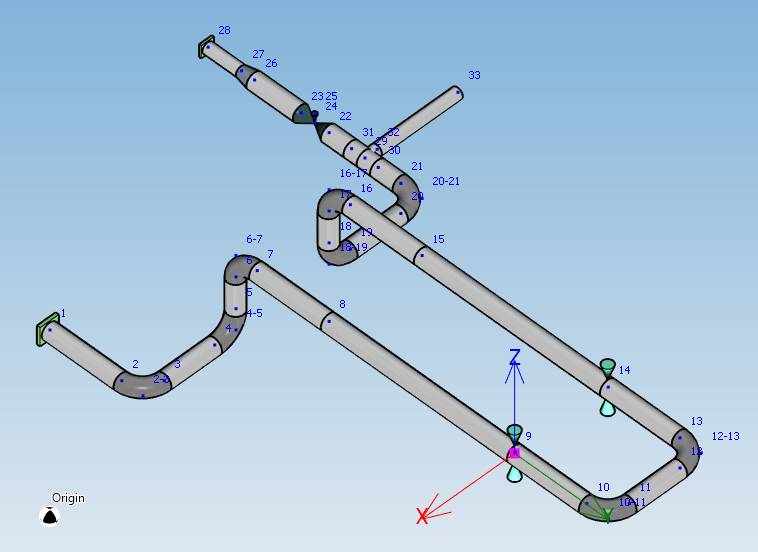
Create a piping study with some restraints on node.
Create a structure study with a link to the previous study.
Select a restrainted node in the link model and press the Support1 button.
This window will appear :
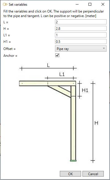
Change values and click OK :
