Create bellows
When you click on the Add bellow button without selection, the left panel shows a message :
Select 1 node
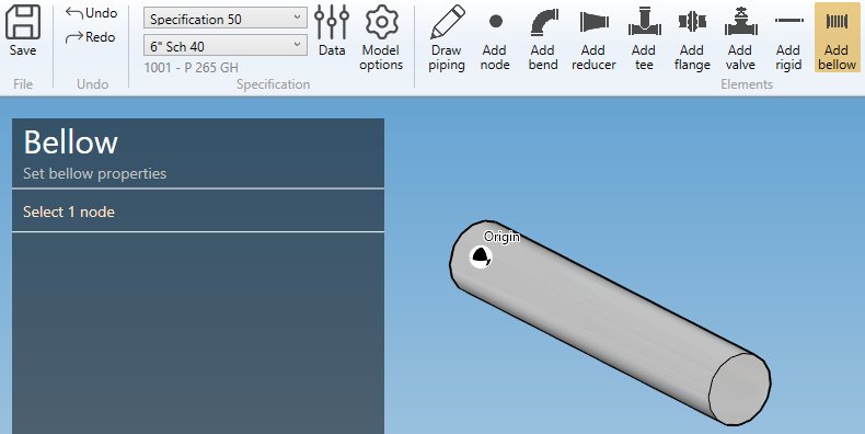
The selection mode is automatically set to POINT. You can so directly select a node.
1. Create a bellow
- Select the current section/material in the specification box.
- Select a node.
- Click the Add bellow button.
By default, the orientation of the element is defined to Insert represented by a blue arrow with direction tangent to the previous element.
You can decide to use the orientation tool to define another direction by unchecking this option. This panel will appear :
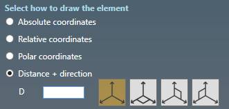
Click here for more information about the orientation tool.
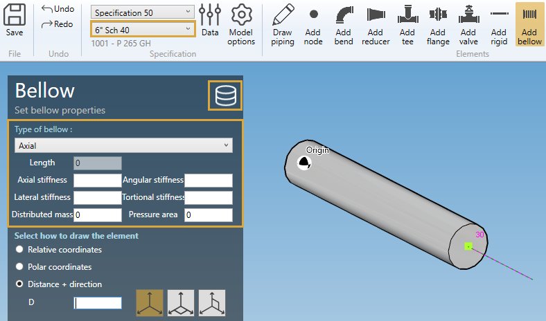
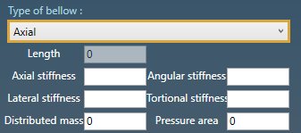
BELLOW PROPERTIES :
- Axial : Axial and lateral displacements and rotations are permitted
- Lateral in a single plane : Lateral displacements are only permitted in the plane defined by the local axes Z’ and X’. No axial displacements nor rotations are permitted
- Lateral in all planes : Lateral displacements are permitted in all directions perpendicular to the element axis Z’. No axial displacements nor rotations are permitted
- Angular in a single plane : Rotations are only permitted about the local axis Y’. The movements are thus restricted to the plane defined by the local axes Z’ and X’
- Angular in all planes : Rotations are permitted about all axes perpendicular to Z’
Based on type, you have to define several properties :
- Axial :
| Property | Unit Metric | Unit USA |
|---|---|---|
| Length | m | ft |
| Axial stiffness | kN/mm | kips/in |
| Lateral stiffness | kN/mm | kips/in |
| Angular stiffness | kN.m/rad | kips.ft/rad |
| Torsional stiffness | kN.m/rad | kips.ft/rad |
| Distributed mass | ton | kips |
| Pressure area | mm² | in² |
If Torsional stiffness is zero or blank, the joint is modeled as rigid in torsion and the user should verify that the moments about the element axis Z’ are acceptable.

One half of the mass will be concentrated at each end of the bellow.
- Lateral in a single plane
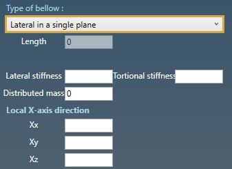
| Property | Unit Metric | Unit USA |
|---|---|---|
| Length | m | ft |
| Lateral stiffness | kN/mm | kips/in |
| Torsional stiffness | kN.m/rad | kips.ft/rad |
| Distributed mass | ton | kips |
If Torsional stiffness is zero or blank, the joint is modeled as rigid in torsion and the user should verify that the moments about the element axis Z’ are acceptable.

One half of the mass will be concentrated at each end of the bellow.
You can define the X-axis vector by defining Xx, Xy, Xz in global coordinates.
- Lateral in all planes
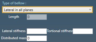
| Property | Unit Metric | Unit USA |
|---|---|---|
| Length | m | ft |
| Lateral stiffness | kN/mm | kips/in |
| Torsional stiffness | kN.m/rad | kips.ft/rad |
| Distributed mass | ton | kips |
If Torsional stiffness is zero or blank, the joint is modeled as rigid in torsion and the user should verify that the moments about the element axis Z’ are acceptable.

One half of the mass will be concentrated at each end of the bellow.
- Angular in a single plane
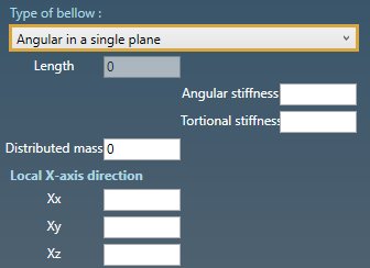
| Property | Unit Metric | Unit USA |
|---|---|---|
| Length | m | ft |
| Angular stiffness | kN.m/rad | kips.ft/rad |
| Torsional stiffness | kN.m/rad | kips.ft/rad |
| Distributed mass | ton | kips |
If Torsional stiffness is zero or blank, the joint is modeled as rigid in torsion and the user should verify that the moments about the element axis Z’ are acceptable.

One half of the mass will be concentrated at each end of the bellow.
- Angular in all planes
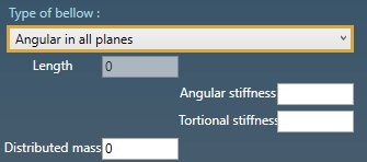
| Property | Unit Metric | Unit USA |
|---|---|---|
| Length | m | ft |
| Angular stiffness | kN.m/rad | kips.ft/rad |
| Torsional stiffness | kN.m/rad | kips.ft/rad |
| Distributed mass | ton | kips |
If Torsional stiffness is zero or blank, the joint is modeled as rigid in torsion and the user should verify that the moments about the element axis Z’ are acceptable.

One half of the mass will be concentrated at each end of the bellow.
DATABASE :
To save time, you can also directly select a bellow from database :
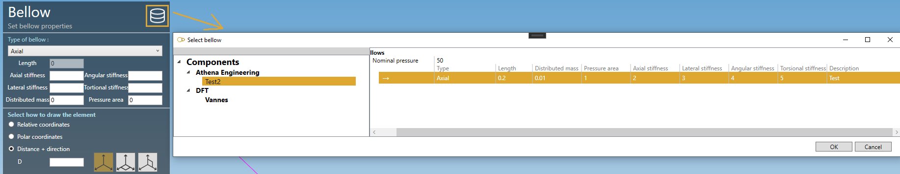
Click on the Database button, select a Library and a Bellow. The OK button will appear.
The tables will be filled automatically.
Click here for more information about creation of library of components.
X-AXIS DIRECTION :
You can define the X-axis vector by defining Xx, Xy, Xz in global coordinates.
Use the left and right keyboard arrows to turn the X-axis vector 90°/-90°around the tangent direction.
LABEL :
You can define a label to this element. The labels are shown with the node names view button.

NEXT NODE :
You can set the next extremity node name of the element. If blank, the software will define it automatically. The software will also check that the name doesn’t already exist.
You can then define the second point of the bellow thanks to the Orientation tool.
Click here for more information about the orientation tool.
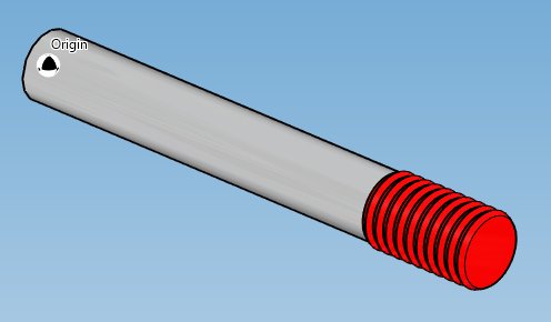
Create the bellow :
2. Modify/Remove a bellow
Change the Selection mode to ELEMENT and select a bellow :
Click here for more information about the selection tool.
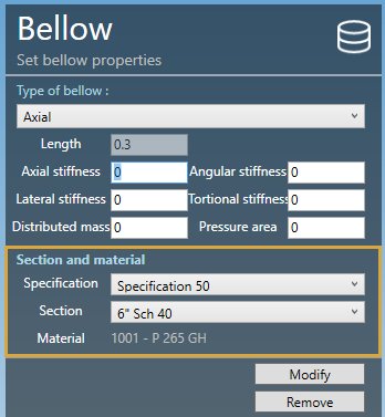
You can change the type and the appropriate properties of the selected bellow (except the length).
SECTION AND MATERIAL :
You can change the specification and section/material of the bellow.
Click on the Modify button to change the selected bellow with these new properties.
You can undo this command.
Click on the Remove button to delete the selected bellow.
You can undo this command.
3. Insert a bellow on an intermediate node
Click on the Add bellow button and select an intermediate node between 2 elements.
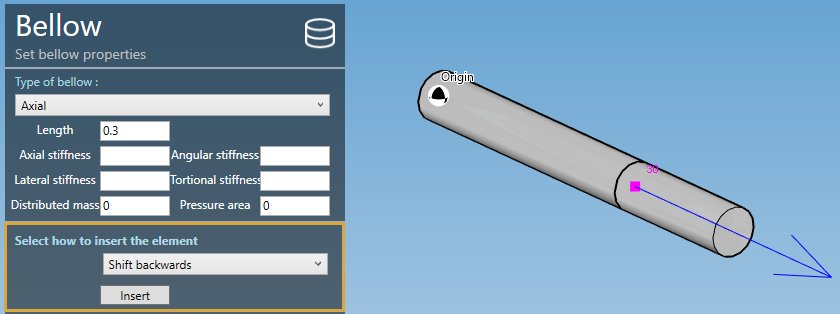
Fill the properties (see §1) and select the insertion mode :
- Shift forward
- Shift backwards
- Reduce the next element
- Reduce the previous element
- Symmetrically reduce the neighboring elements
ATTENTION, if the length is null, no mode will be proposed (empty list)
Based on the length of the bellow and the lengths of the neighboring elements, some mode could be hidden.
Select for example “Shift backwards” and click the Insert button :
You can undo this command.