Orientation
This tool is common to all elements.
The goal is to help user to set the second extremity node, based on the first selected one.
1. Absolute coordinates
This mode is useful when you want to draw an element with the second node defined in absolute global coordinates :
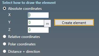
| Property | Unit Metric | Unit USA |
|---|---|---|
| X | m | ft |
| Y | m | ft |
| Z | m | ft |
To know the UNIT of the value, just let the mouse over the cell.
Click the Create element button to create the element.
You can Undo this command.
2. Relative coordinates
This mode is useful when you want to draw an element with the second node relative to the first one in the global axis directions :
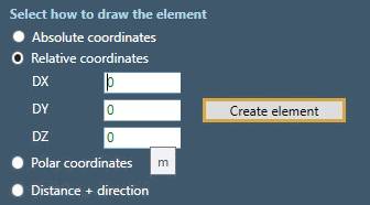
| Property | Unit Metric | Unit USA |
|---|---|---|
| DX | m | ft |
| DY | m | ft |
| DZ | m | ft |
To know the UNIT of the value, just let the mouse over the cell.
TIP : a preview of the element length will be shown when entering values :
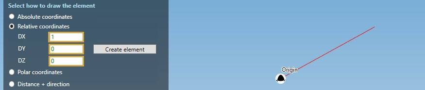
Click the Create element button to create the element.
You can Undo this command.
3. Polar coordinates
This mode is useful when you want to draw an element with the second point relative to the first one by a distance and 2 angles :
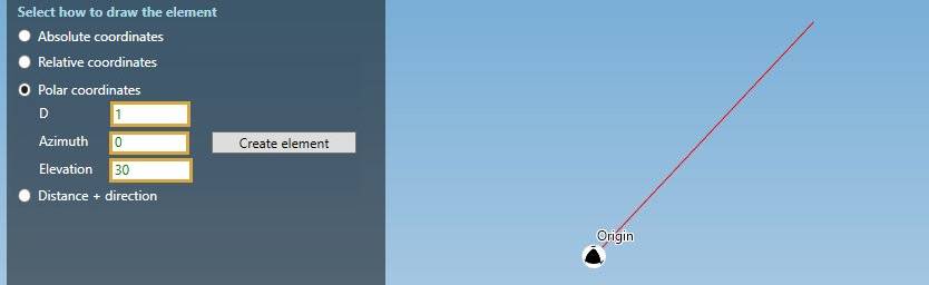
| Property | Description Unit | Metric | Unit USA |
|---|---|---|---|
| D | Distance | m | ft |
| Azimuth | Horizontal angle | ° | ° |
| Elevation | Vertical angle | ° | ° |
To know the UNIT of the value, just let the mouse over the cell.
TIP : a preview of the element length will be shown when entering values.
Click the Create element button to create the element.
You can Undo this command.
4. Distance + direction
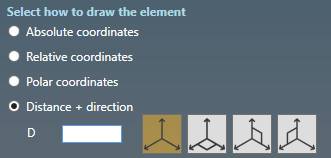
This mode is useful when you want to draw an element with a standard direction (+X, -X, +Y, -Y, +Z, -Z) and a distance from the first node :
| Property | Unit Metric | Unit USA |
|---|---|---|
| Distance | m | ft |
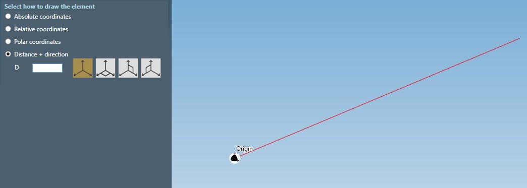
Move the mouse in the desired direction. The line will take the same color as the global axis. Red for X, green for Y and blue for Z.
Write the distance on the keyboard (m or ft) :
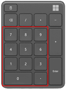
The value will automatically be entered in the corresponding cell (D).
Click on Enter to execute the creation.
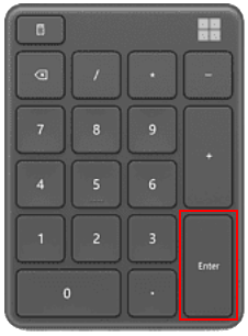
ATTENTION, do not write the value in the cell directly !
You can Undo this command.
4.1 Horizontal plane
Click on the second button to display a horizontal graduated wheel :
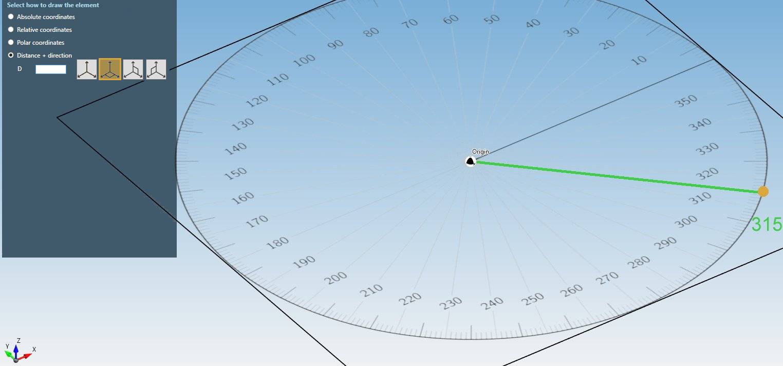
Bring mouse closer to an angle to be magnetized (Ex : at 315 °).
Now that the direction is established, as in §3, write the distance on the keyboard :
And validate :
The second node will be at “Distance” from the first node in the direction of the selected angle.
4.2 Vertical plane
Click on the third button to display a vertical graduated wheel :
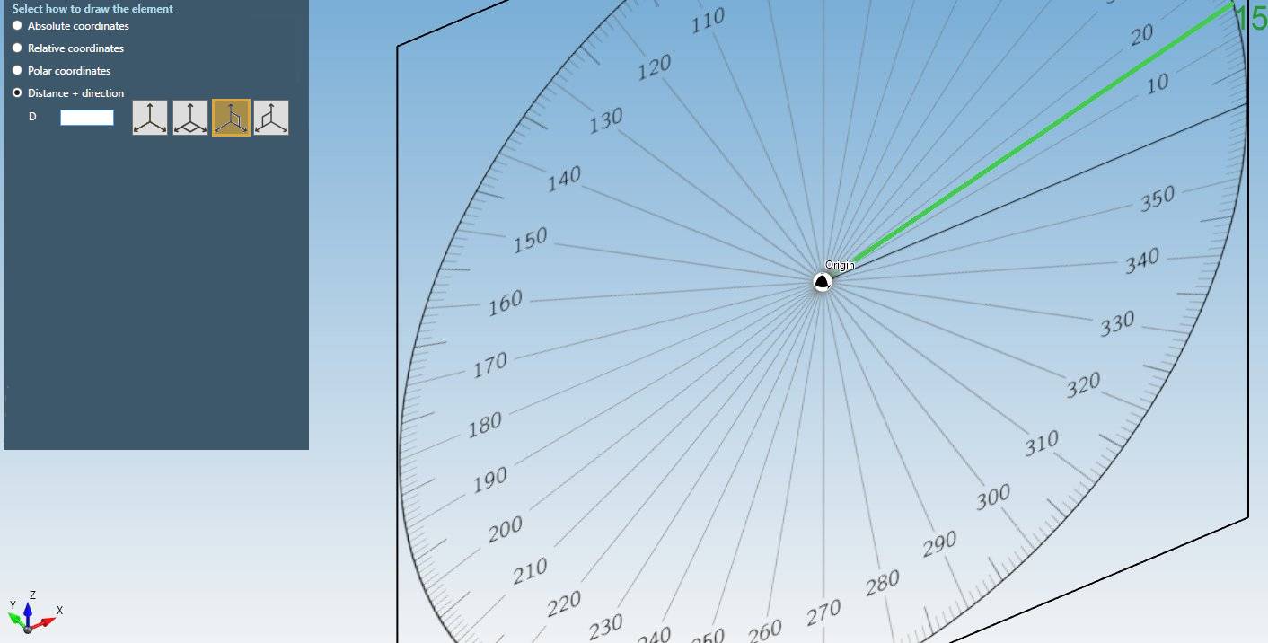
Bring mouse closer to an angle to be magnetized (Ex : at 15 °).
Now the direction is established, as in §3., write the distance on the keyboard :
And validate :
The second node will be at “Distance” from the first node in the direction of the selected angle.
You can Undo this command.
The last button is the vertical plane perpendicular to the element.
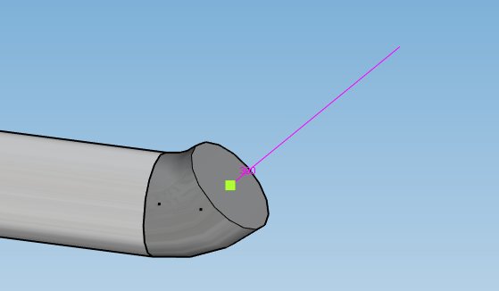
4.3 Special cases
- Tangent direction (in MAGENTA) :
- Snap to an existing node (for branch connection - in YELLOW) :
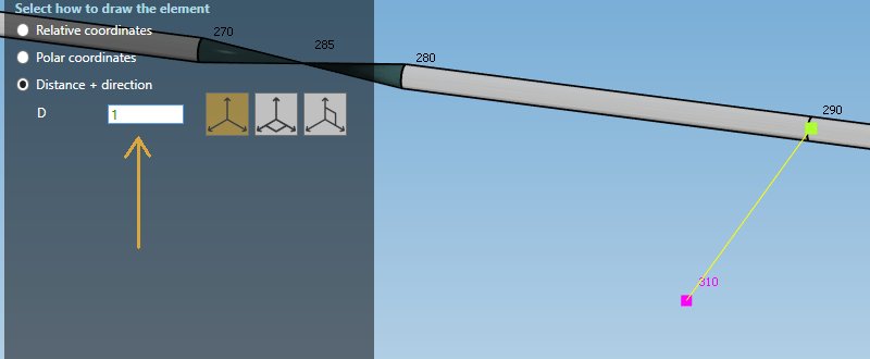
TIP : The distance is automatically filled in the cell. Press ENTER to create the element :
The point (GREEN) becomes a REFERENCE point
You can Undo this command.
- Indication of similar coordinate with a REFERENCE point :
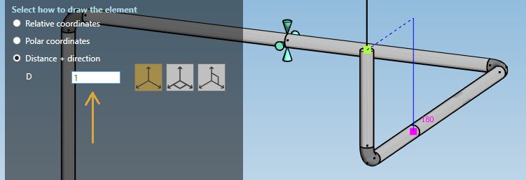
- Snap to a point (become the new REFERENCE POINT in GREEN)
- Move mouse vertically from the first point and wait that the dashed lines appear.
- The blue line indicates that the Z coordinate is similar to the coordinate of the REFERENCE point. Same for the dashed lines.
- The distance is automatically filled in the cell.
- Press ENTER to create the element :
You can Undo this command.