Modification
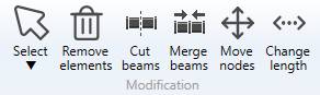
1. Selection
Click on Select button to open the selection window :
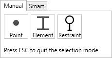
- Click on Point to select nodes (or F10)
- Click on Element to select elements (beam, rigid and spring) (or F11)
- Click on Restraint to select restraints (or F12)
- Press ESC on keyboard to hide the selection window
You can now select objects of the corresponding type.
The selection is done by pressing the left mouse button above the desired object
Click here to have more information about the selection.
2. Measure tool
See Mesure tool in Review for more info.
3. Remove elements
Select elements and click the Remove elements button to delete these elements.
You can Undo this command.
4. Cut beams
When you click on the Cut beams button without selection, the left panel shows a message :
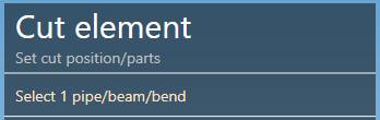
The selection mode is automatically set to ELEMENT. You can so directly select a beam.
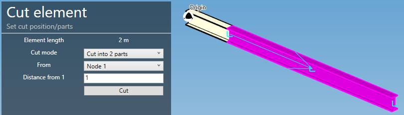
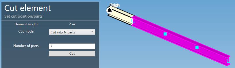
Cut mode can be :
- Cut into 2 parts
- Cut into N parts
The current length of the beam is shown on top.
By default, a distance from the first node of the beam is calculated, which is the half length of the selected beam (middle point).
You can choose from which node to start and the distance.
| Property | Unit Metric | Unit USA |
|---|---|---|
| Length | m | ft |
| Distance | m | ft |
Click on Cut to execute the command.
To know the UNIT of the value, just let the mouse over the cell.
You can Undo this command.
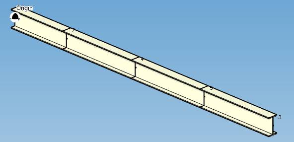
The second possibility is to cut in N parts with preview :
Click on the Cut button :
You can Undo this command.
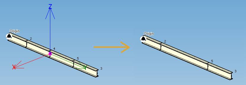
5. Merge beams
Select a Node between 2 similar colinear beams and click the Merge button.
The 2 beams must have the same Material and the same Section.
The 2 beams will be replaced by one beam.
Attention, the force, restraint, lumped mass or local coordinates defined on the node will be destroyed.
You can Undo this command.
6. Move nodes
When you click on the Move nodes button without selection, the left panel shows a message :
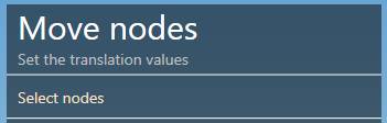
The selection mode is automatically set to POINT. You can so directly select nodes.
Select the nodes one by one (with CTRL) or by a selection rectangle :
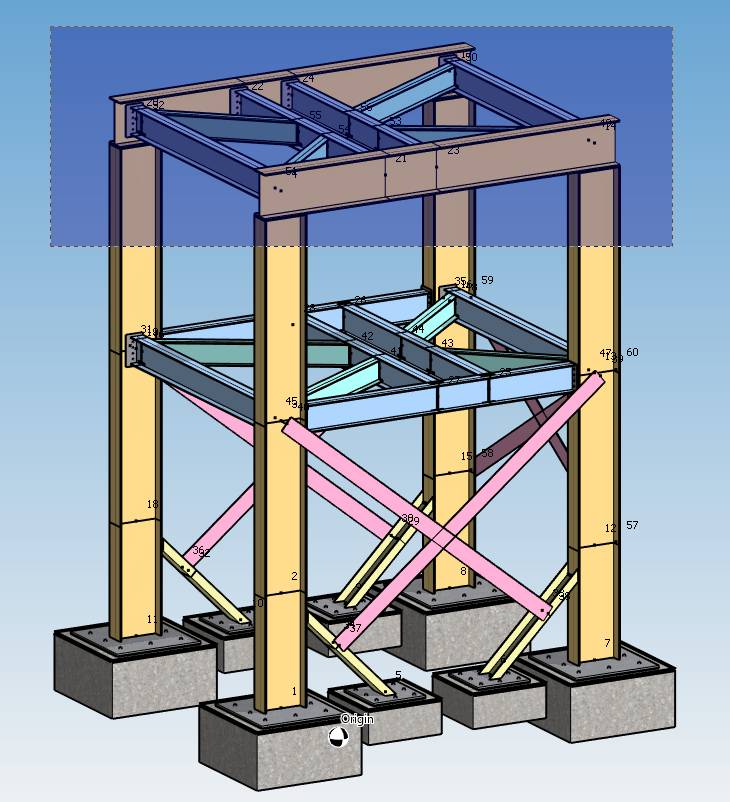
You can move nodes in translation, rotation or mirror.
6.1 Translation
Set the offset to apply to the selected nodes :
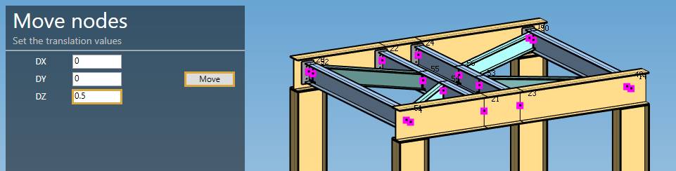
| Property | Unit Metric | Unit USA |
|---|---|---|
| DX | m | ft |
| DY | m | ft |
| DZ | m | ft |
Validate the command by clicking the Move button :
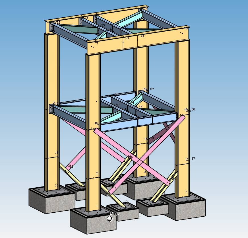
You can Undo this command.
6.2 Rotation
Set the rotation center, the rotation axis and the angle of rotation around this axis :
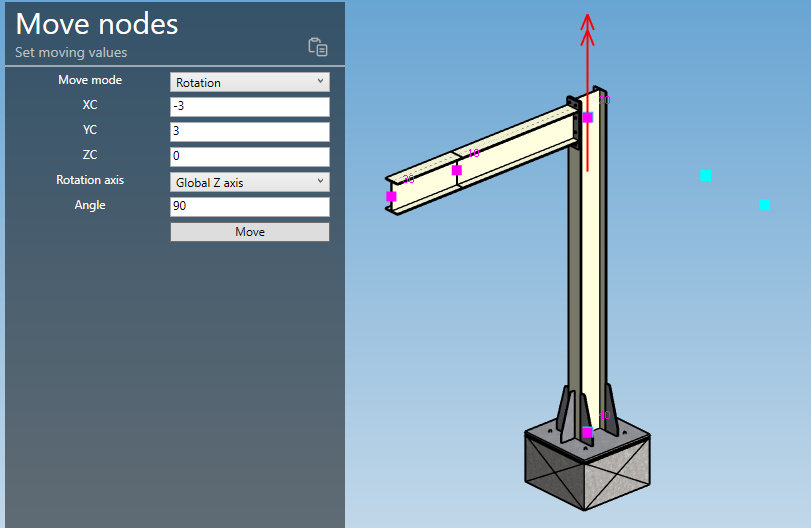
| Property | Unit Metric | Unit USA |
|---|---|---|
| XC | m | ft |
| YC | m | ft |
| ZC | m | ft |
| Angle | degree | degree |
REM : you can paste previously copied node coordinates with upper right  button.
Click here for more information about the selection of a node.
Validate the command by clicking on the Move button :
You can Undo this command.
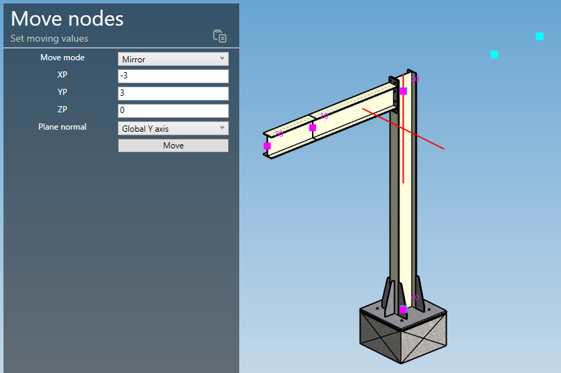
6.3 Mirror
Set the mirror point and the plane normal :
| Property | Unit Metric | Unit USA |
|---|---|---|
| XP | m | ft |
| YP | m | ft |
| ZP | m | ft |
REM : you can paste previously copied node coordinates with upper right button.
Click here for more information about the selection of a node.
Validate the command by clicking on the Move button :
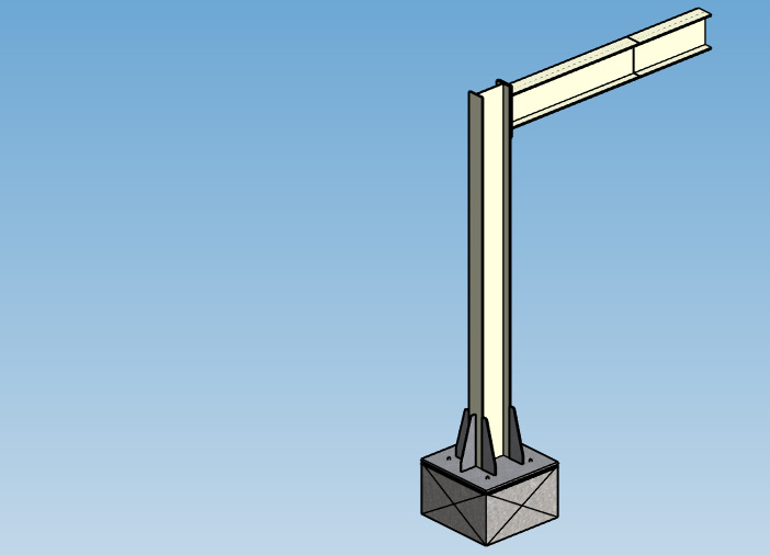
You can Undo this command.
ATTENTION, if there is external node linked to structural node, the link will be invalid. Remove the link (and the eventual U-bolt) before moving node.
7. Change length/direction
When you click on the Change length button without selection, the left panel shows a message :
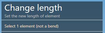
The selection mode is automatically set to ELEMENT. You can so directly select an element (beam, rigid or spring).
Change mode :
- Change length
- Change direction
You can select only one element.
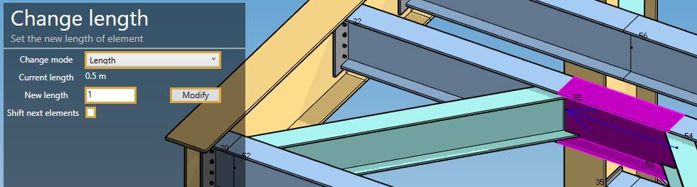
7.1 Change length
Select an element and set the new length :
| Property | Unit Metric | Unit USA |
|---|---|---|
| Length | m | ft |
Set the new length to 1 and uncheck the Shift cell.
Click on the Modify button :
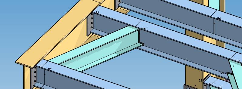
The point 55 moved.
The graphical ending of the “green” beam and the welding have been automatically recalculated !
You can Undo this command.
7.2 Change direction
Select an element and set the mode Direction :
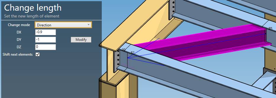
The panel shows the actual DX, DY, DZ
Set the new direction (DX, DY, DZ) and uncheck the Shift cell :
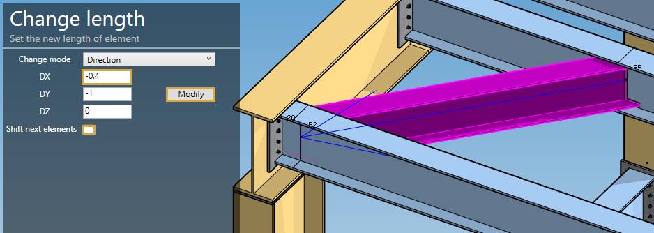
Click on the Modify button :
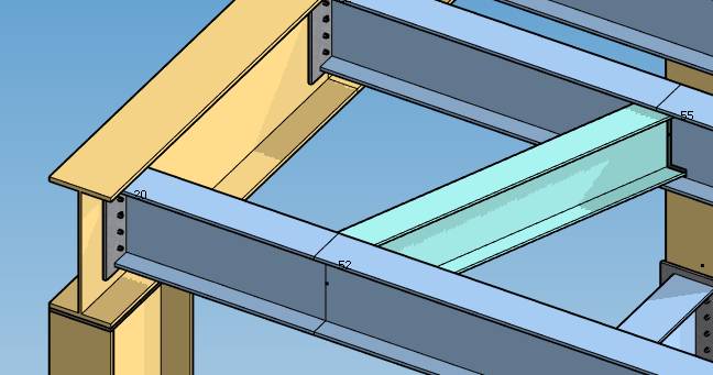
The point 52 moved.
The graphical ending of the “green” beam and the welding have been automatically recalculated !
You can Undo this command.
8. Copy elements
MetaStructure lets you copy elements (without the loads).
Copy mode :
- Translation
- Rotation
- Mirror
ATTENTION, MetaStructure does not check the position of the new nodes. Under no circumstances can they coincide with existing nodes.
8.1 Translation
Select the elements and define the translation vector :

| Property | Unit Metric | Unit USA |
|---|---|---|
| DX | m | ft |
| DY | m | ft |
| DZ | m | ft |
Set the number of repetition of the copy (default = 1).
ATTENTION, the restraint, node and element properties, DLCS, lump masses will also be copied but not the loads on the elements or nodes.
A preview shows where the copy will take place.
Click on the Copy button :

8.2 Rotation
Select the elements, define the position of the global center of rotation, the axis and the angle :

| Property | Unit Metric | Unit USA |
|---|---|---|
| XC | m | ft |
| YC | m | ft |
| ZC | m | ft |
| Angle | ° | ° |
Set the number of repetition of the copy (default = 1).
REM : you can paste previously copied node coordinates with upper right button.
Click here for more information about the selection of a node.
ATTENTION, the restraint, node and element properties, DLCS, lump masses will also be copied but not the loads on the elements or nodes.
A preview shows where the copy will take place.
Click on the Copy button :

8.3 Mirror
Select the elements, define the position of a global point of the mirror plane and the plane normal :

| Property | Unit Metric | Unit USA |
|---|---|---|
| XP | m | ft |
| YP | m | ft |
| ZP | m | ft |
REM : you can paste previously copied node coordinates with upper right button.
Click here for more information about the selection of a node.
ATTENTION, the restraint, node and element properties, DLCS, lump masses will also be copied but not the loads on the elements or nodes.
A preview shows where the copy will take place.
Click on the Copy button :

9. Properties
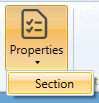
9.1 Section
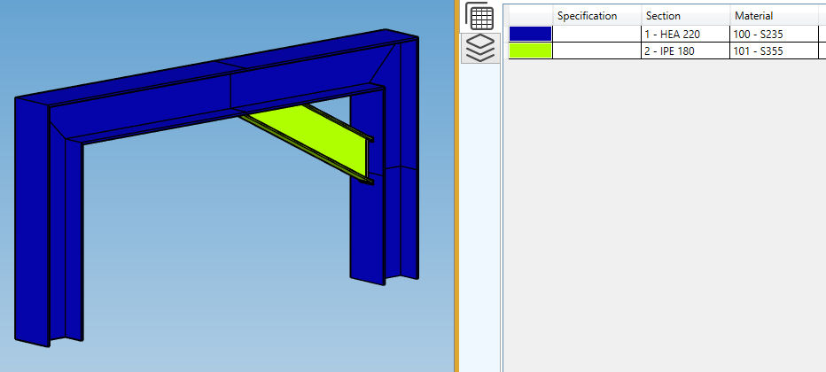
As in review, the Section property shows all sections used in the model with a colored map :
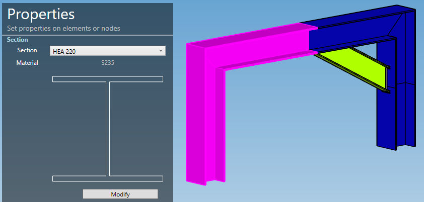
MetaStructure lets you change the section of multiple elements in one operation.
Select multiple elements, a section, and click on the Modify button :
You can Undo this command.
Remarks :
The section proposed are those from Data screen.
If the sections are different between several selected elements, Variable will appear. You have to specify the wanted new section to be able to modify.