Modification
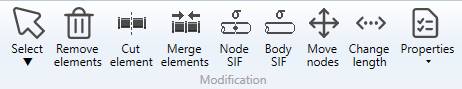
1. Selection
Click on Select button to open the selection window :
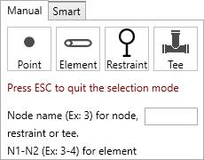
- Click on Point to select nodes (or F10)
- Click on Element to select piping elements (pipe, bend, reducer, valve, etc.) (or F11)
- Click on Restraint to select restraints (or F12)
- Click on Tee to select nodes where a tee has been assigned
- Press ESC on keyboard to hide the selection window
You can now select objects of corresponding type.
The selection is done by pressing the left mouse button above the desired object
You can also select a node by entering the node name and click to the Point button.
You can also select an element by entering the two node names separate by “-“ and click to the Element button.
You can also select a valve by entering its label and click to the Element button.
You can also select a restraint by entering the node name or its label and click to the Restraint button.
Click here to have more information about the selection.
2. Measure tool
See Mesure tool in Review for more info.
3. Remove nodes, elements and restraints
Select nodes, elements or restraints and click on the Remove elements button to delete these elements.
You can Undo this command.
The nodes must be isolated (not an extremity or part of an element)!
4. Cut element
It is possible to cut pipe, bend and beam and in several parts.
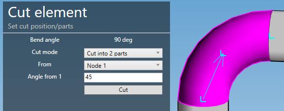
Select for example one pipe and click to the Cut element button :
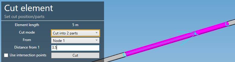
Cut mode can be :
- Cut into 2 parts
- Cut into N parts
The current length of the pipe is shown on top.
By default, a distance from the first node of the pipe is calculated, which is the half length of the selected pipe (middle point).
You can choose from which node to start and the distance.
| Property | Unit Metric | Unit USA |
|---|---|---|
| Length | m | ft |
| Distance | m | ft |
If the pipe has a bend before, next or both, you can check the cell Use intersection point to calculate the distance between these points instead of the extremities of the pipe.
If the position of the cut is outside the selected element, the cut button will not works.
Click on Cut to execute the command.
To know the UNIT of the value, just let the mouse over the cell.
You can Undo this command.
The second possibility is to cut in N parts with preview :
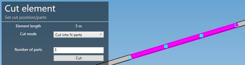
The tool is available only for pipes, beams and bends. For bends, length and distance are replaced by angles :
5. Merge elements
Select a Node between 2 similar colinear pipes or 2 succesive bends with same center and radius, and click on the Merge button.
The 2 pipes/bends must have the same Material and the same Section.
The 2 pipes/bends will be replaced by one pipe/bend.
Attention, the force, restraint, lumped mass or local coordinates defined on the node will be destroyed.
You can Undo this command.
6. Node SIF
MetaPiping lets you define Stress Intensification Factors and Stress Indices on nodes.
Each piping code has its own factors.
| Code | SIFS |
|---|---|
| ASME and RCC-M Class 1 | B1, C1, K1, B2, C2, K2, C3, C3’, K3 |
| ASME Class 2 | i, B1, B2, B2’, C2 |
| B31.1 up to ed. 2018 | i |
| B31.1 ed. 2020 (B31J) | ii, io, it, ia, Ii, Io, It, Ia |
| EN 13480 | io, ii |
| RCC-M Class 2 | i |
| RCC-MRx | B1, C1, K1, B2, C2, K2, C3, K3, D1, D21, D22, D23 |
These factors are unitless.
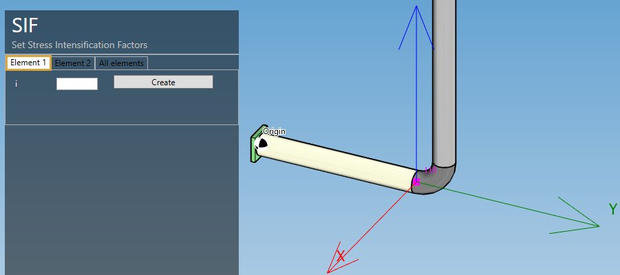
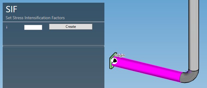
Select a node and click on the Node SIF button.
- You can change one (or more) factor(s) at the extremity of the first element connected to the node, e.g. in RCC-M Class 2 code :
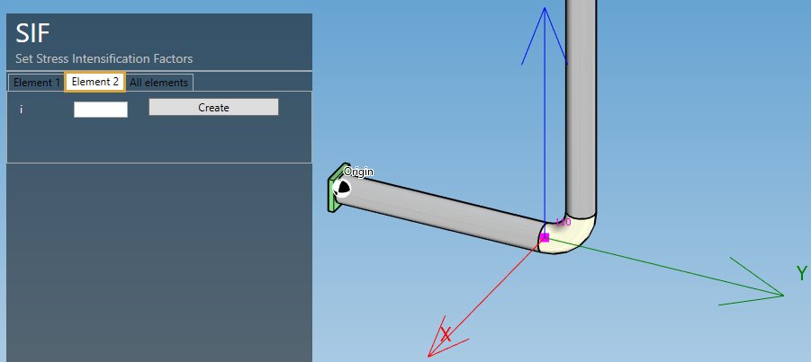
- You can change one (or more) factor(s) at the extremity of the second element connected to the node :
- You can change one (or more) factor(s) of all elements :
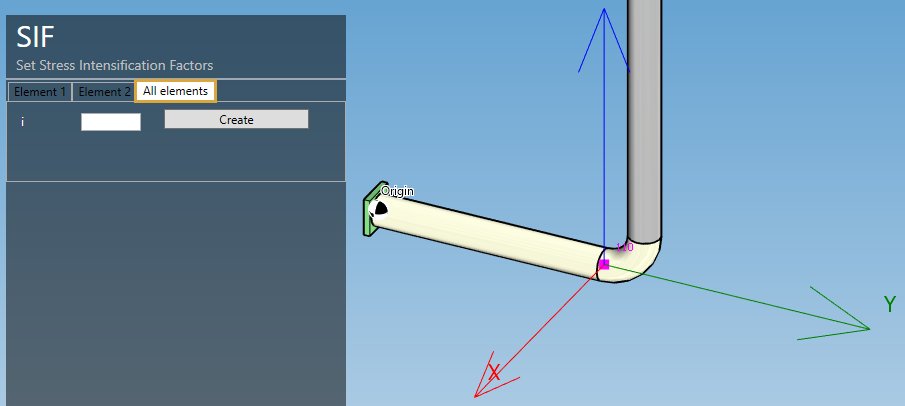
Click on Apply button to apply the SIFs to the model.
You can later modify or remove the SIFs by selecting the node and clicking on Modify/Remove buttons.
You can Undo this command.
7. Body SIF
MetaPiping lets you define Stress Intensification Factors and Stress Indices on elements.
Select an element and click on the Body SIF button :
Click on Apply button to apply the SIFs to the model.
You can later modify or remove the SIFs by selecting the element and clicking on Modify/Remove buttons.
You can Undo this command.
8. Move nodes
MetaPiping lets you move nodes.
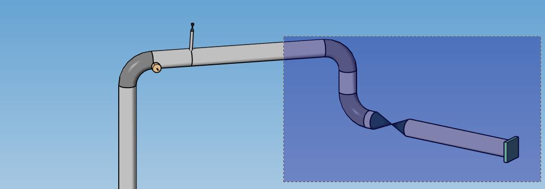
Select the nodes one by one (with CTRL) or by a selection rectangle :
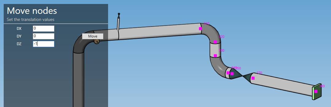
Set the offset to apply to the nodes :
| Property | Unit Metric | Unit USA |
|---|---|---|
| DX | m | ft |
| DY | m | ft |
| DZ | m | ft |
Validate the command by clicking on the Move button :
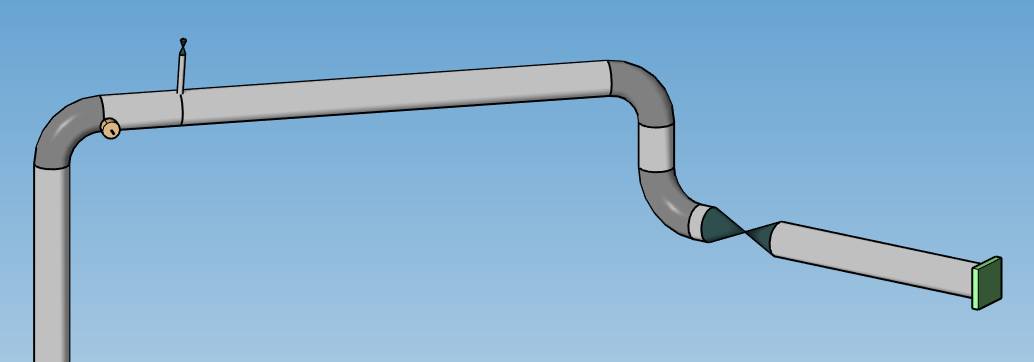
You can Undo this command.
ATTENTION, sometimes this modification can create unwanted results, essentially due to bend definition no more compatible. You have to remove elements and rebuild the connection.
Remove bend :
Select the 2 nodes :
Click on the Add bend button, set the section and the radius, click on the Create button :
This will extend the 2 adjacent elements and place a bend with the desired radius.
9. Change length/direction
MetaPiping lets you change length of any element (no bend).
Change mode :
- Change length
- Change direction
You can select only one element.
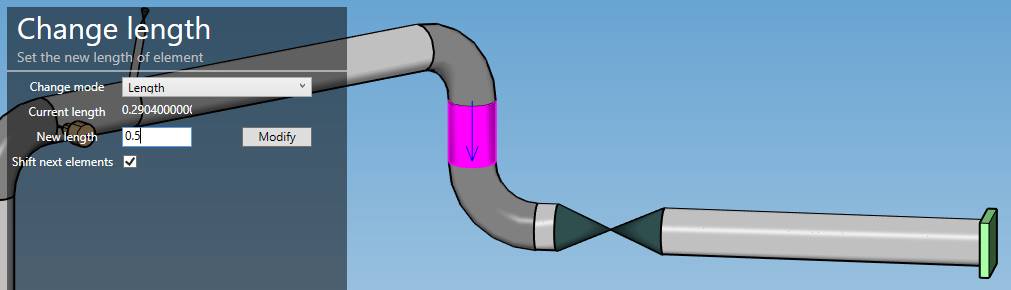
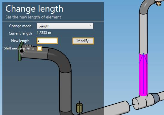
9.1 Change length
Select an element and set the new length :
| Property | Unit Metric | Unit USA |
|---|---|---|
| Length | m | ft |
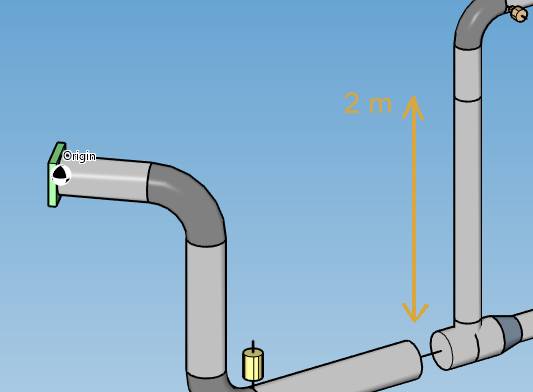
The Shift option offsets all following elements.
If Shift option is unchecked, MetaPiping will try to change the length of the selected element and modify the length of the next element.
A new length of 0 will remove the element if possible (the element must not be the attached element of a restraint)
You can Undo this command.
For eccentric reducer, the change length tool let you change the angle of alignement:
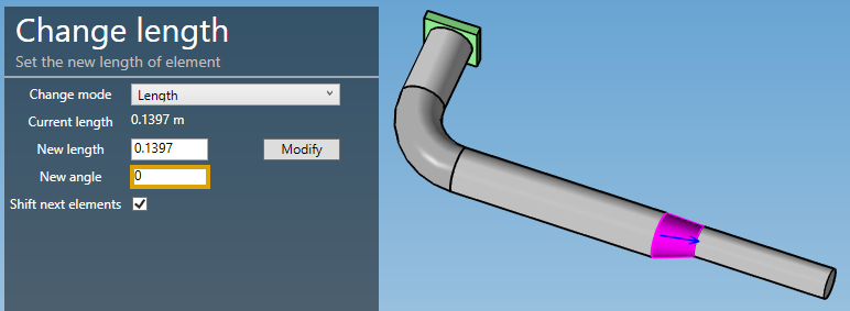
Don’t forget to shift the next elements to not destroy the pipeline continuity.
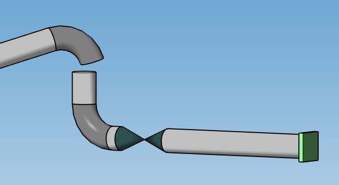
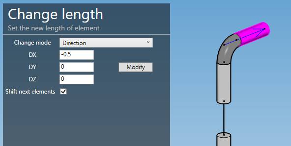
9.2 Change direction
Select an element and set the new length vector (DX, DY, DZ) :
| Property | Unit Metric | Unit USA |
|---|---|---|
| DX | m | ft |
| DY | m | ft |
| DZ | m | ft |
ATTENTION, the vector (DX, DY, DZ) is calculated from intersection point to intersection point. On the last picture, the arrow starts from the intersection point on the bend and ends at the last point of the pipe.
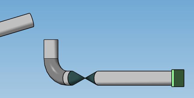
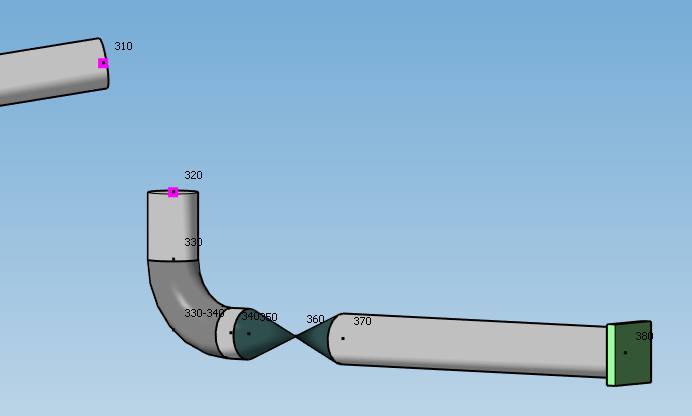
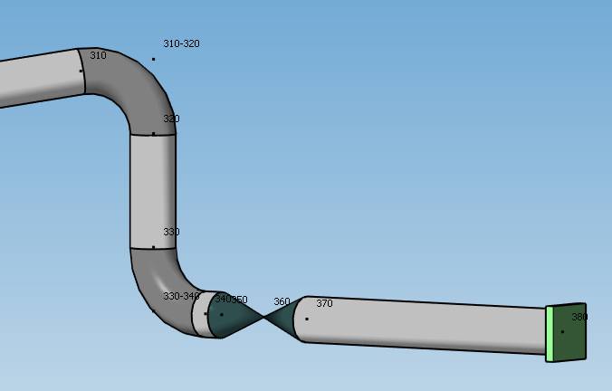
Let’s try this change of direction :
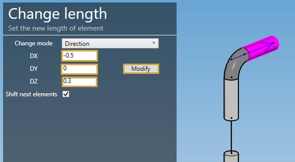
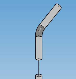
The Shift option offsets all following elements.
ATTENTION, sometime this modification can create unwanted results, essentially due to bend definition no more compatible. You have to remove elements and rebuild the connection. See §7 that show an example of how to rebuild a bend.
You can Undo this command.
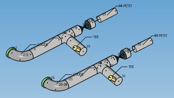
10. Copy elements
MetaPiping lets you copy elements (without the loads).
Copy mode :
- Translation
- Rotation
- Mirror
ATTENTION, MetaPiping does not check the position of the new nodes. Under no circumstances can they coincide with existing nodes.
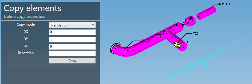
10.1 Translation
Select the elements and define the translation vector :
| Property | Unit Metric | Unit USA |
|---|---|---|
| DX | m | ft |
| DY | m | ft |
| DZ | m | ft |
Set the number of repetition of the copy (default = 1).
ATTENTION, the restraint, node and element properties, DLCS, lump masses, SIFs will also be copied but not the loads on the elements or nodes.
A preview shows where the copy will take place.
Click on the Copy button :
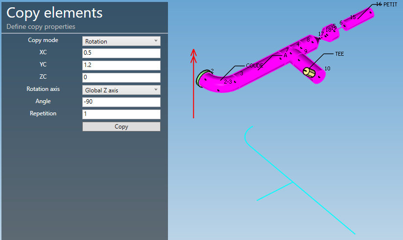
10.2 Rotation
Select the elements, define the position of the global center of rotation, the axis and the angle :
| Property | Unit Metric | Unit USA |
|---|---|---|
| XC | m | ft |
| YC | m | ft |
| ZC | m | ft |
| Angle | ° | ° |
Set the number of repetition of the copy (default = 1).
ATTENTION, the restraint, node and element properties, DLCS, lump masses, SIFs will also be copied but not the loads on the elements or nodes.
A preview shows where the copy will take place.
Click on the Copy button :
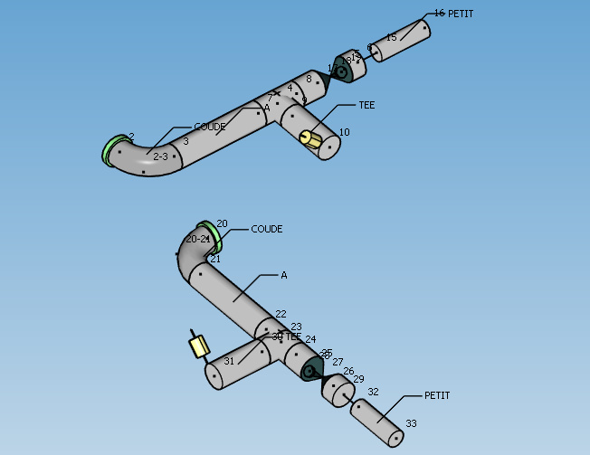
10.3 Mirror
Select the elements, define the position of a global point of the mirror plane and the plane normal :
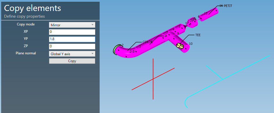
| Property | Unit Metric | Unit USA |
|---|---|---|
| XP | m | ft |
| YP | m | ft |
| ZP | m | ft |
ATTENTION, the restraint, node and element properties, DLCS, lump masses, SIFs will also be copied but not the loads on the elements or nodes.
A preview shows where the copy will take place.
Click on the Copy button :
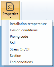
11. Properties
11.1 Installation temperature
MetaPiping lets you define installation temperature of elements when different from default one :
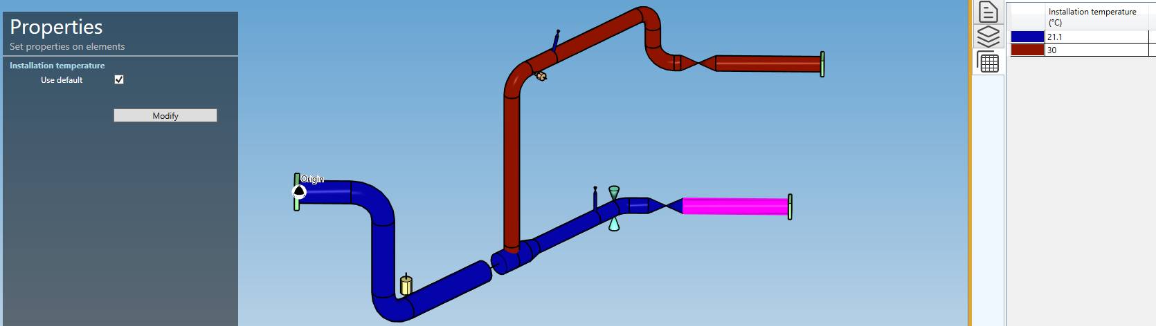
Select multiple elements, uncheck Use default cell and set the new temperature.
| Property | Unit Metric | Unit USA |
|---|---|---|
| Temperature | °C | °F |
Click on Modify to validate.
You can see the elements with this property by a colored map and the legend in the right tab.
You can Undo this command.
11.2 Design conditions
MetaPiping lets you define the design conditions of elements when different from default one :
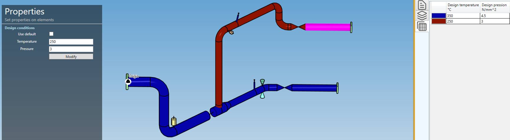
Select multiple elements, uncheck Use default cell and set the temperature and pressure.
| Property | Unit Metric | Unit USA |
|---|---|---|
| Temperature | °C | °F |
| Pressure | N/mm² | psi |
Click on Modify to validate.
You can see the elements with this property by a colored map and the legend in the right tab.
You can Undo this command.
11.3 Piping code
MetaPiping lets you define the piping code of elements when different from default one :
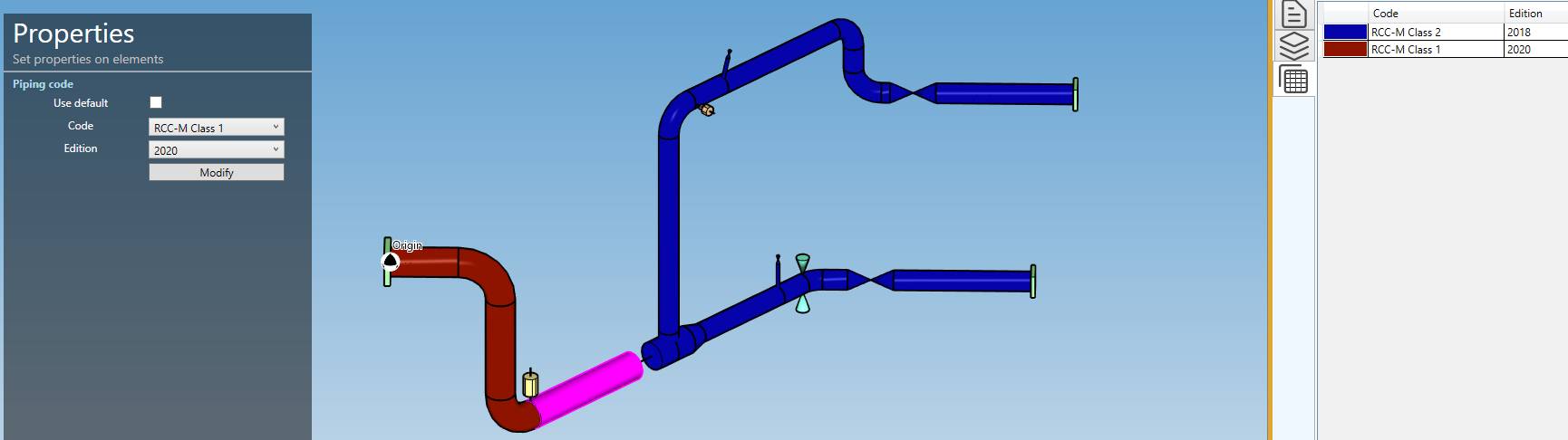
Select multiple elements, uncheck Use default cell and set the new code and edition.
Click on Modify to validate.
You can see the elements with this property by a colored map and the legend in the right tab.
You can Undo this command.
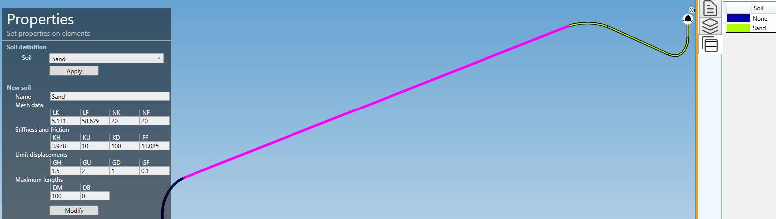
11.4 Soil
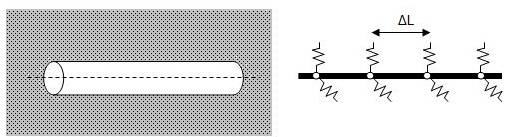
In Buried piping, soils must be defined for all elements.
The soil is modeled as a Winkler foundation. Discrete springs are placed at regular intervals ∆L along the piping in the transverse and axial directions. The springs can be either elastic or elastic-plastic.
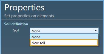
Select multiple elements and choose New soil :
Give it a name and fill the soil properties :
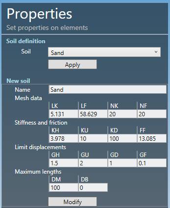
| Property | Description | Unit Metric | Unit USA |
|---|---|---|---|
| LK | Influence length | m | in |
| LF | Slippage length | m | in |
| NK | Number of transverse springs along the influence length | - | - |
| NF | Number of axial springs along the slippage length | - | - |
| KH | Horizontal modulus of subgrade reaction | N/mm² | ksi |
| KU | Vertical upwards modulus of subgrade reaction | N/mm² | ksi |
| KD | Vertical downwards modulus of subgrade reaction | N/mm² | ksi |
| FF | Maximum unit friction force at the pipe/soil interface | kN/m | kips/ft |
| GH | Pipe displacement at maximum horizontal resistance | mm | in |
| GU | Pipe displacement at maximum upwards resistance | mm | in |
| GD | Pipe displacement at maximum downwards resistance | mm | in |
| GF | Axial pipe displacement at maximum friction force | mm | in |
| DM | Maximum pipe length | m | ft |
| DB | Maximum bend length | m | ft |
Click on Modify to validate.
You can see the elements with this property by a colored map and the legend in the right tab.
You can Undo this command.
11.5 Stress On/Off
MetaPiping lets you deactivate the stress report of a portion of the piping system.
Select multiple elements and click on the Deactivated stress button :
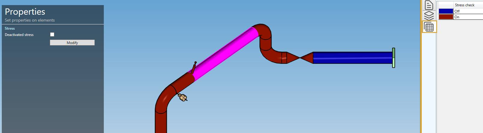
Click on the Modify button to deactivate the stress reporting of these elements.
You can later modify this property by selecting the elements and activating or deactivating the checkbox.
You can see the elements with this property by a colored map and the legend in the right tab.
You can Undo this command.
11.6 Section
As in review, the Section property shows all sections used in the model with a colored map :
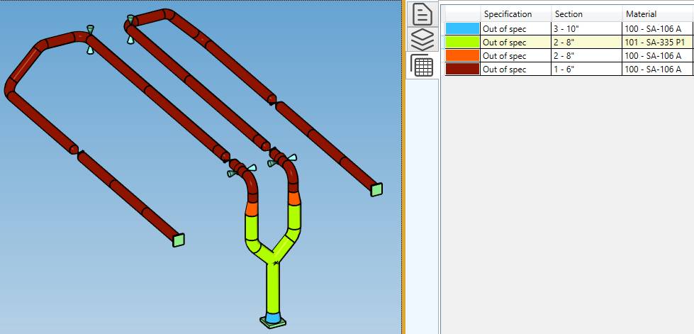
MetaPiping lets you change the section of multiple elements in one operation.
Select multiple elements, a specification and a section, and click on the Modify button :
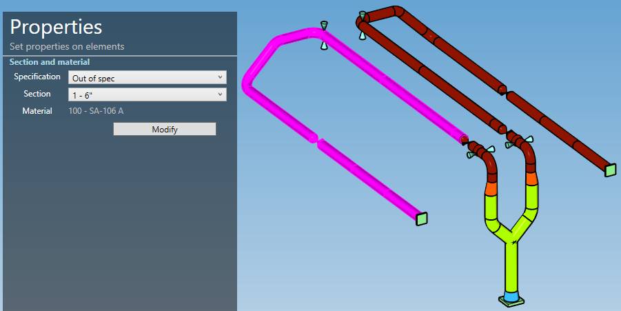
You can Undo this command.
If the sections are different between several selected elements, Variable will appear. You have to specify the wanted new section to be able to modify.
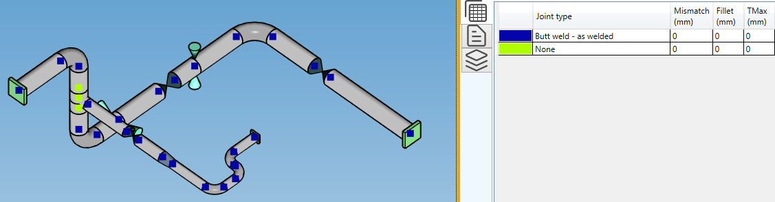
11.7 End conditions
The End conditions property shows all type of joint between elements with a colored map :
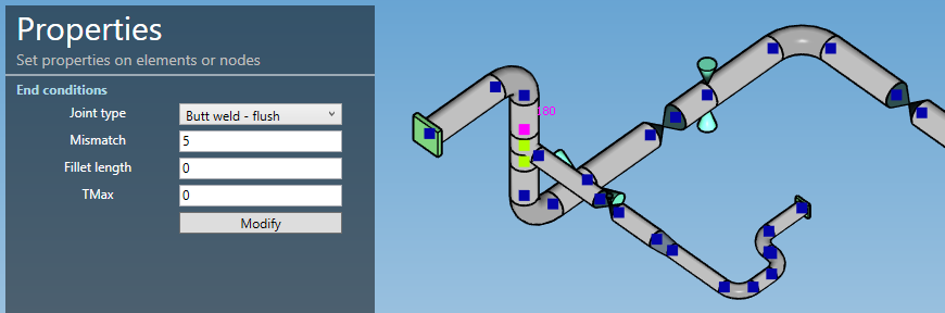
MetaPiping lets you change the joint of multiple nodes in one operation.
Select multiple nodes, change the properties, and click on the Modify button :
You can Undo this command.
If the types are different between several selected nodes, Variable will appear. You have to specify the wanted new type to be able to modify.