Piping review
1. Ribbon menu
2. Data panel
A right panel can be opened by clicking on the top button. It presents the selected data :
Click on the same button to hide the panel. Shortcut = F2.
TIP : you can copy the data by CTRL+C and paste in other software.
3. Measure tool
MetaPiping lets you measure the distance between 2 nodes :
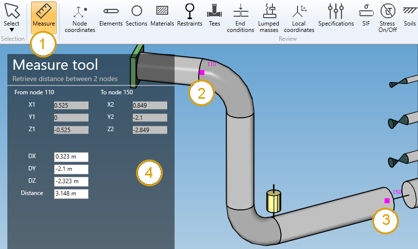
- Select the Measure tool
- Select the first node
- Select the second node without CTRL pressed
- The distances appear on the left panel
You can continue to select other nodes, only the 2 last ones will be taken in account.
The name and the coordinates of the two nodes will be shown.
| Property | Description | Unit Metric | Unit USA |
|---|---|---|---|
| DX | Distance on global X | m | ft |
| DY | Distance on global Y | m | ft |
| DZ | Distance on global Z | m | ft |
| Distance | Distance between the 2 nodes | m | ft |
The Selection mode is automatically set to POINT when clicking the Measure button.
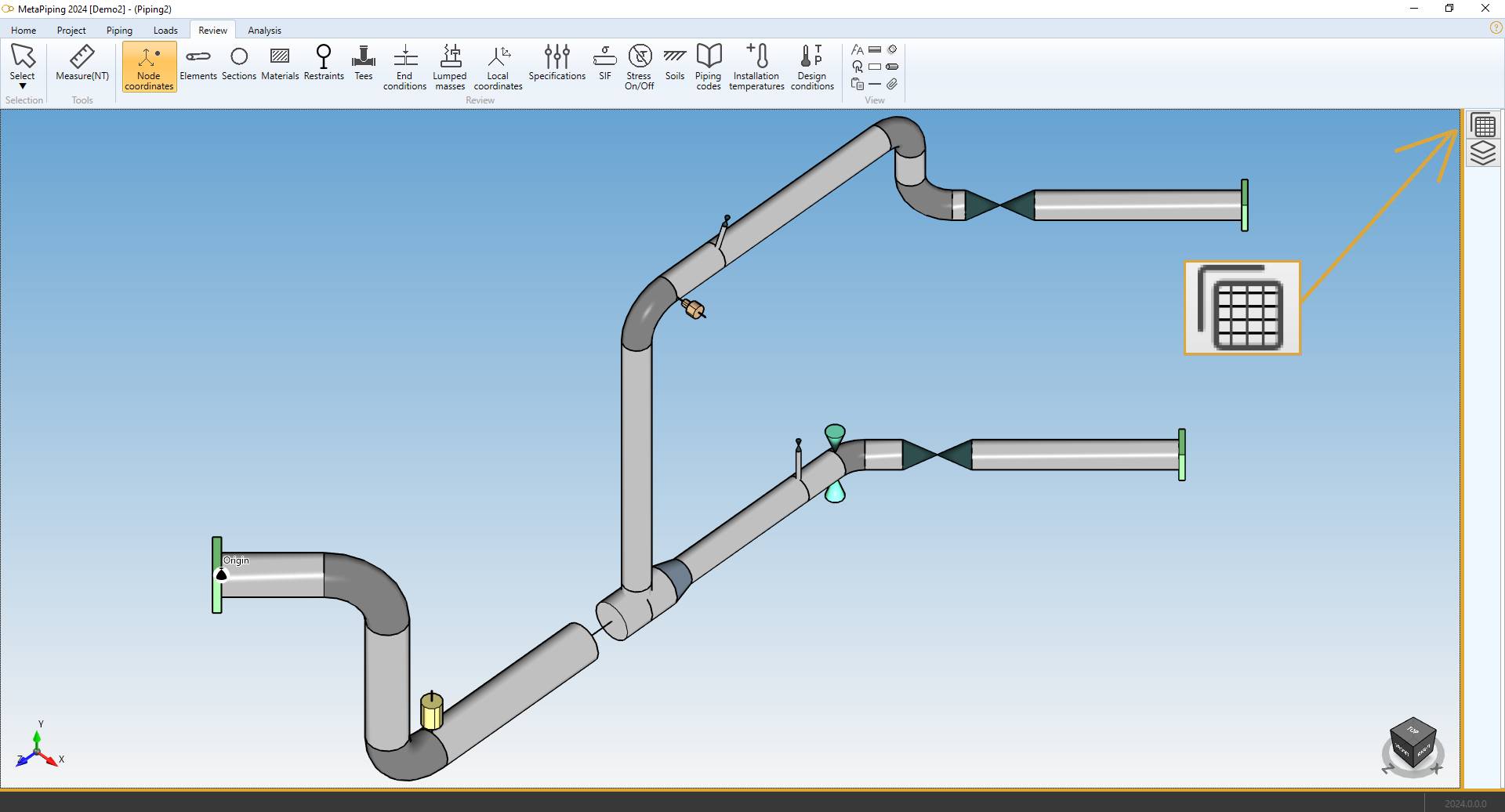
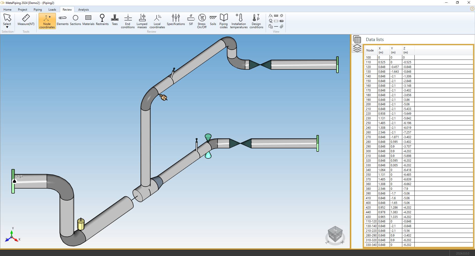
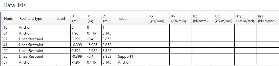
4. Node coordinates
Click on the Node coordinates button :
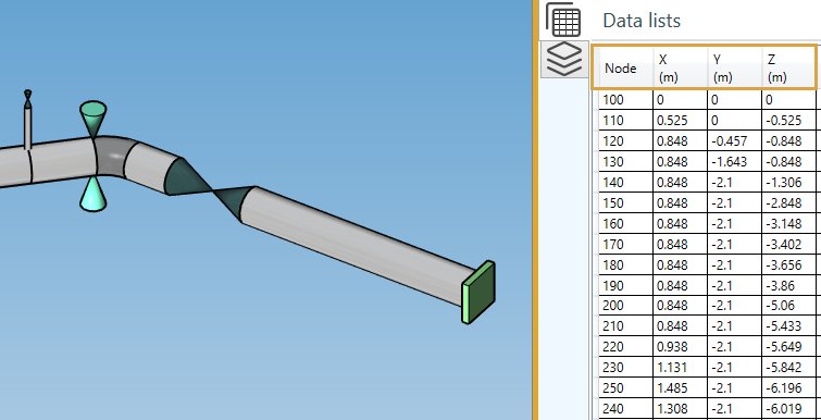
The Data panel shows the global coordinates X, Y, Z for each node.
| Property | Description | Unit Metric | Unit USA |
|---|---|---|---|
| Node name | Text or number | - | - |
| X | X global coordinate | m | ft |
| Y | Y global coordinate | m | ft |
| Z | Z global coordinate | m | ft |
The Selection mode is automatically set to POINT
INTERACTIVITY :
- Select a node in the model (1) will highlight the corresponding row in the data list (2) :
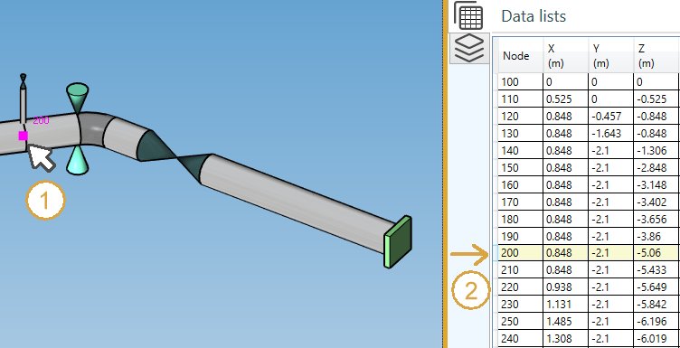
- Select a row in the data list (1) will highlight the corresponding node in the model (2) :
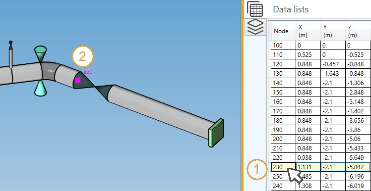
The data are not editable
5. Elements
Click on the Elements button :
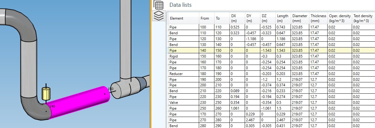
| Property | Unit Metric | Unit USA |
|---|---|---|
| Element type | - | - |
| Node1 name | - | - |
| Node2 name | - | - |
| DX | m | ft |
| DY | m | ft |
| DZ | m | ft |
| Length | m | ft |
| Diameter | mm | in |
| Thickness | mm | in |
| Operating density | - | - |
| Test density | - | - |
| Bend radius | mm | in |
| Label | - | - |
The INTERACTIVITY is the same as explained on §5.
The data are not editable
6. Sections
Click on the Sections button :
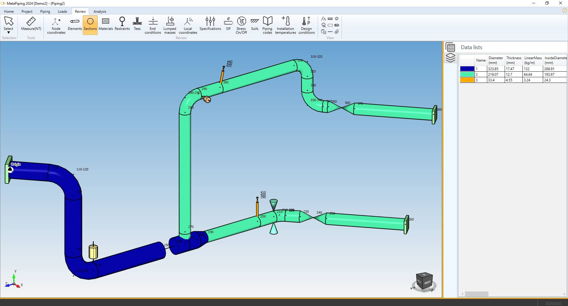
The piping elements are colorized in the color of their corresponding section.
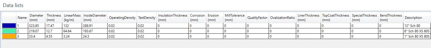
| Property | Unit Metric | Unit USA |
|---|---|---|
| Section color | - | - |
| Name | - | - |
| Diameter | mm | in |
| Thickness | mm | in |
| Linear mass | kg/m | lb/ft |
| Inside diameter | mm | in |
| Operating density | - | - |
| Test density | - | - |
| Insulation thickness | mm | in |
| Corrosion | mm | in |
| Erosion | mm | in |
| Mill tolerance | mm | in |
| Quality factor | - | - |
| Ovalization ratio | - | - |
| Liner thickness | mm | in |
| Topcoat thikness | mm | in |
| Special thickness | mm | in |
| Bend thickness | mm | in |
| Description | - | - |
The data are not editable
7. Materials
Click on the Materials button :
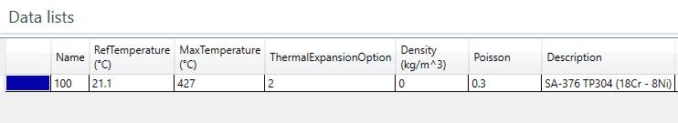
The piping elements are colorized in the color of their corresponding material.
| Property | Unit Metric | Unit USA |
|---|---|---|
| Material color | - | - |
| Name | - | - |
| Ref temperature | °C | °F |
| Max temperature | °C | °F |
| Thermal expansion option | - | - |
| Density | kg/m³ | lb/ft³ |
| Poisson | - | - |
| Description | - | - |
The data are not editable
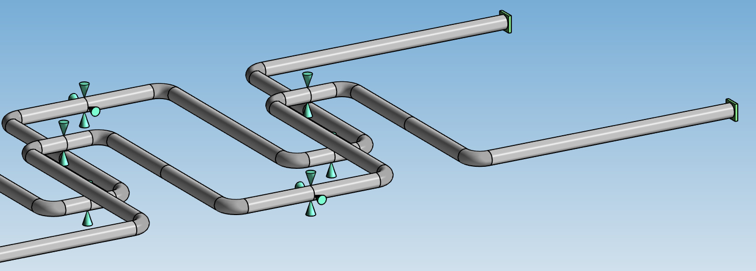
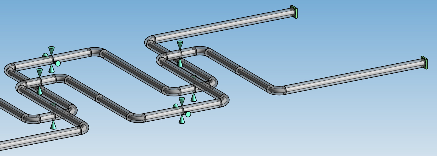
8. Restraints
Click on the Restraints button :
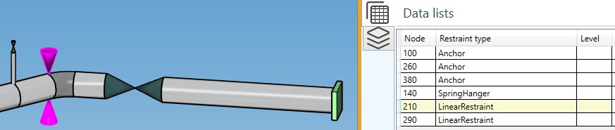
The Data panel shows the Restraint type and the Level for each restraint.
The INTERACTIVITY is the same as explained on §5.
The label and modified Spring Constants are shown :
The data are not editable
9. Tees
Click on the Tees button :
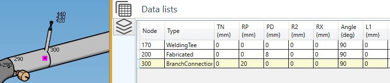
| Property | Description | Unit Metric | Unit USA |
|---|---|---|---|
| TN | Branch connections and lateral connections reinforcement thickness | mm | in |
| RP | Branch Outer Radius | mm | in |
| PD | Pad thickness for reinforced fabricated tees | mm | in |
| R2 | Branch-to-run fillet radius | mm | in |
| RX | Transition radius | mm | in |
| Angle | Angle header/branch | ° | ° |
| L1 | Branch reinforcement length | mm | in |
The INTERACTIVITY is the same as explained on §5.
The data are not editable
10. End conditions
Click on the End conditions button :
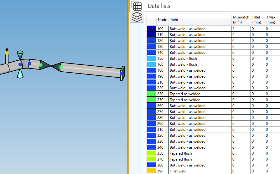
Small colored squares show the joint type of the nodes. Joint type None is not shown for better readability.
| Property | Unit Metric | Unit USA |
|---|---|---|
| Color | - | - |
| Node name | - | - |
| Joint type | - | - |
| Mismatch | mm | in |
| Fillet length | mm | in |
| TMax | mm | in |
The INTERACTIVITY is the same as explained on §5.
The data are not editable
11. Lumped masses
Click on the Lumped masses button :
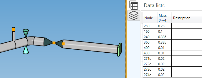
The lump masses on node, the mass of flange, valve, bellow, socket, structural and rigid are shown.
| Property | Unit Metric | Unit USA |
|---|---|---|
| Node name | - | - |
| Mass | ton | kips |
| Description | - | - |
Click here for more information about creation of lumped mass on node.
The INTERACTIVITY is the same as explained on §5.
The data are not editable
12. Local coordinates
Click on the Local coordinates button :
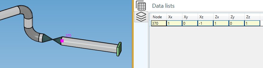
| Property | Unit Metric | Unit USA |
|---|---|---|
| Node name | - | - |
| Xx | - | - |
| Xy | - | - |
| Xz | - | - |
| Zx | - | - |
| Zy | - | - |
| Zz | - | - |
Click here for more information about creation of local coordinates on node.
The INTERACTIVITY is the same as explained on §5.
The data are not editable
13. Specifications
Click on the Specifications button :
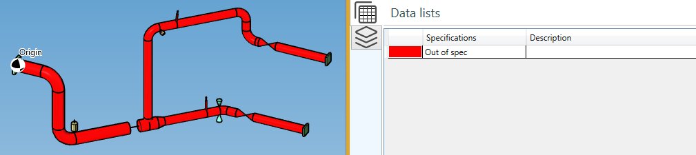
In case of more than one specification (Out of spec), the elements will follow the color of the specification that it respects.
Small colored squares will show the specification of the tees.
The data are not editable
Click here for more information about creation of specification.
14. SIF
MetaPiping lets you define Stress Intensification Factors on nodes and elements.
Click on the SIF button :
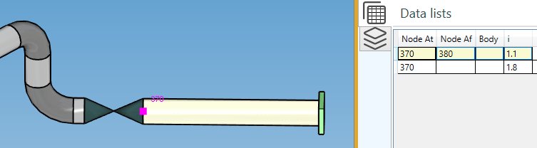
| Property | Definition |
|---|---|
| At Node name | The node where the SIF are defined |
| Af Node name | Empty if SIF on all elements (extremities) - otherwise only on the element (extremity) defined by the Af node |
| Body | Yes if SIF on element - Empty if SIF on node |
If Body = Yes, Node At and Node Af correspond to the nodes of the element
Click here for more information about creation of Stress Intensification Factors on nodes and elements.
Each piping code has its own factors.
| Code | SIFS |
|---|---|
| ASME Class 1 | B1, C1, K1, B2, C2, K2, C3, CP, K3 |
| ASME Class 2 | i, B1, B2, B2’, C2 |
| B31.1 | i |
| B31.1 B31.J | ii, io, it, ia, Ii, Io, It, Ia |
| EN 13480 | io, ii |
| RCCM Class 2 | i |
The INTERACTIVITY is the same as explained on §5.
The data are not editable
15. Stress On/Off
Click on the Stress On/Off button :
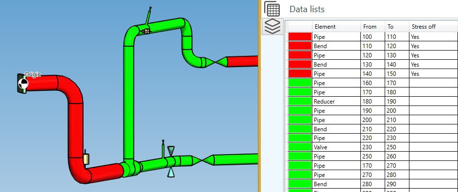
| Property | Definition |
|---|---|
| Color | Red = stress reporting off - Green = stress reporting on |
| Element type | - |
| From | Element Node1 name |
| To | Element Node2 name |
| Stress off | Yes or empty |
Click here for more information about Stress On/Off definition.
The data are not editable
16. Soils
Click on the Soils button :
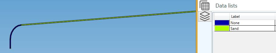
Click here for more information about soil definition.
The data are not editable
17. Piping codes
Click on the Piping codes button :
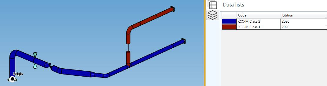
Click here for more information about piping code definition.
The data are not editable
18. Installation temperatures
Click on the Installation temperatures button :
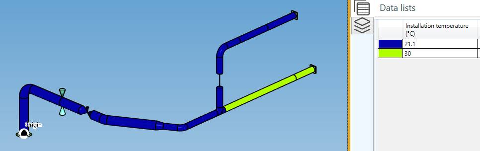
| Property | Unit Metric | Unit USA |
|---|---|---|
| Color | - | - |
| Installation temperature | °C | °F |
Click here for more information about installation temperature definition.
The data are not editable
19. Design conditions
Click on the Design conditions button :
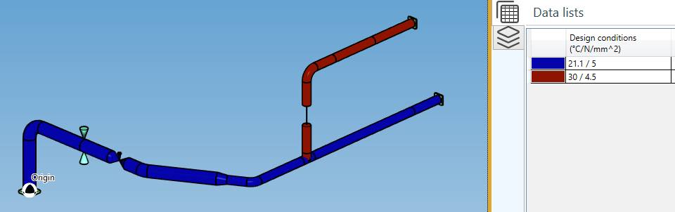
| Property | Unit Metric | Unit USA |
|---|---|---|
| Color | - | - |
| Design conditions (Temperature // Pressure) | °C // N/mm² | °F // lb/in² |
Click here for more information about design condition definition.
The data are not editable
20. View options
 show/hide the node name
 show/hide the node point
 shows/hides the labels
 shows/hides the origin symbol
 shows/hides the masses
 modify the font
 show the structure in shaded mode
 show the structure in hidden lines mode
 show the structure in wireframe mode
 shows/hides the restraints
 increase the restraint’s size
 decrease the restraint’s size
 shows/hides the linked and structure study models
copy the 3D view to the clipboard
 shows/hides the inner pipes
This last tool is usefull to see the piping elements inside others :