Create nodes
There are 3 possibilities of creation :
- Creation of the FIRST node
- Creation of a GLOBAL node
- Creation of a RELATIVE node
1. First node
The first node panel is called when a first element needs a starting point. Example for a pipe :
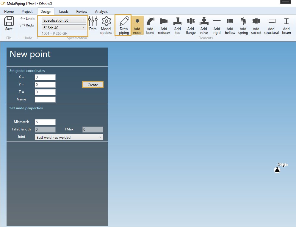
Set the GLOBAL X, Y, Z coordinates and a name.
See Global node just below :
2. Global node
If the selection is EMPTY, click on the Add node button to create a new global node :
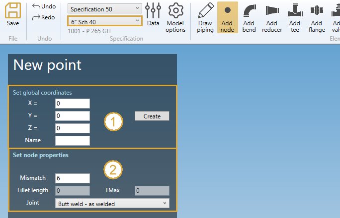
ATTENTION, the current specification is important (Ex : 6” Sch 40) for the default node connection.
Fill the GLOBAL X, Y, Z coordinates and a name (1).
| Property | Description | Unit Metric | Unit USA |
|---|---|---|---|
| X | X global coordinate | m | ft |
| Y | Y global coordinate | m | ft |
| Z | Z global coordinate | m | ft |
| Name | Text or number | - | - |
To know the UNIT of the value, just let the mouse over the cell.
If Name is blank, the new node will receive an automatic name based on the Node settings.
Click here for more information about node naming.
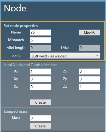
All new node follow the current specification node connection properties (2) :
| Property | Description | Unit Metric | Unit USA |
|---|---|---|---|
| Mismatch | Mismatch for welded joints | mm | in |
| Fillet length | Length of fillet weld Cx | mm | in |
| TMax | for Class 1 transition within 1:3 slope envelope | mm | in |
The Joint can be :
- None
- Butt weld - flush
- Butt weld - as welded
- Fillet weld
- Full fillet weld
- Threaded
- Brazed
In this example, the values correspond to current specification preset :

Click the Create button to create the first node of the model.
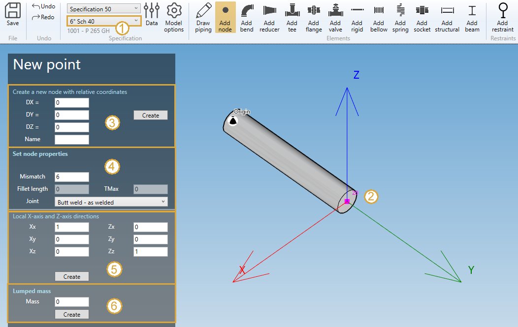
3. Relative node
If a node is selected, you can create a new node relative to it in Global directions :
- Select the current section/material in the specification box.
- Select a node.
- Define the DX, DY, DZ, name of the new node.
- Define the node properties
Click here for more information about the selection tool.
| Property | Description | Unit Metric | Unit USA |
|---|---|---|---|
| DX | Relative distance from the selected node in X global direction | m | ft |
| DY | Relative distance from the selected node in Y global direction | m | ft |
| DZ | Relative distance from the selected node in Z global direction | m | ft |
| Name | Text or number | - | - |
If Name is blank, the new node will receive an automatic name based on the Node settings.
Click here for more information about node naming.
All new node follow the current specification node connection properties (2) :
| Property | Description | Unit Metric | Unit USA |
|---|---|---|---|
| Mismatch | Mismatch for welded joints | mm | in |
| Fillet length | Length of fillet weld Cx | mm | in |
| TMax | max thickness for Class 1 transition within 1:3 slope envelope, or thrust collar thickness for composite | mm | in |
The Joint depends on the material :
Steel
- None
- Butt weld - flush
- Butt weld - as welded
- Fillet weld
- Capped end
- Full fillet weld
- Tapered transition - flush
- Tapered transition - as welded
- Threaded
- Brazed
- One third slope transition - flush
- One third slope transition - as welded
- Lap flange
- Double weld slip-on flange
- Single weld slip-on flange
Composite
- None
- Bell and spigot adhesive bonded
- Bell and spigot adhesive bonded with laminated fiberglass overlay
- Bell and spigot gasket with laminated fiberglass overlay
- Butt and strap
HDPE
- None
- Concentric fabricated reducer
- Thrust collar
- Electrofusion coupling
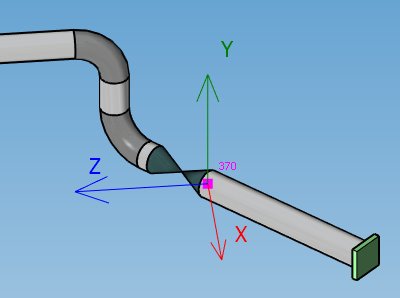
4. Creation of a local coordinate system
You can define a new local coordinate system on selected node (5) :
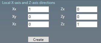
Just define the new X axis vector (Xx, Xy, Xz) in global coordinates and the new Z axis vector (Zx, Zy, Zz). The Y axis will be automatically defined by the right-hand rule.
Example :
Click on the Create button to add a new local coordinate system to the model.
You can later modify or remove this object by selecting this node and click on Modify/Remove buttons.
You can Undo this command.
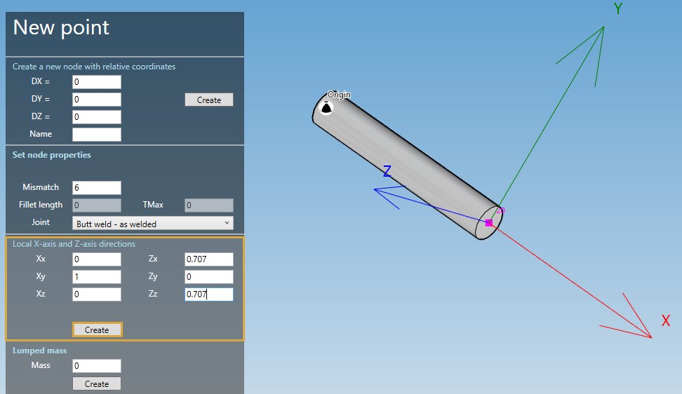
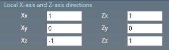
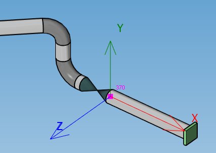
Another example with an off-axis piping :
The default global axis are :
To define the Local X-axis tangent to the pipe, change the vectors like this :
5. Creation of a lumped mass
You can define a lumped mass on selected node (6) :
| Property | Unit Metric | Unit USA |
|---|---|---|
| Mass | ton | kips |
Click on the Create button to add a new lumped mass to the node.
You can later modify or remove this object by selecting this node and click on Modify/Remove buttons.
You can Undo this command.
6. Modify a node
Change the Selection mode to POINT and select a node :
Click here for more information about the selection tool.
You can change the node properties.
Click on the Modify button to change the selected node.
You can Undo this command.