Create beams
When you click on the Add beam button without selection, the left panel shows a message :
Select 1 node
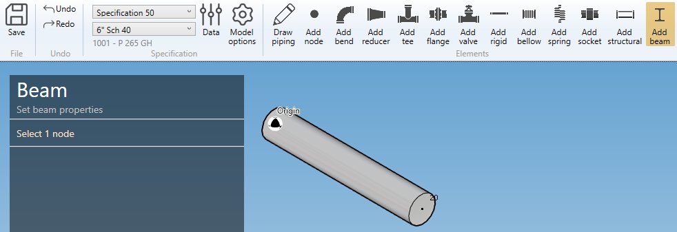
The selection mode is automatically set to POINT. You can so directly select a node.
1. Create a beam
- Select a node.
- Click the Add beam button.
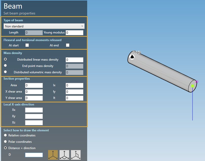
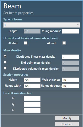
BEAM TYPE :
- Non standard
- I
- Channel
- Rectangular
- Tee
- Equal angle
- Unequal angle
- Round
- Plate
The length must be defined by the orientation tool.
Common property :
| Property | Unit Metric | Unit USA |
|---|---|---|
| Young modulus | kN/mm² | 10^6.psi |
| Moments released | - | - |
| Distributed linear mass density | kg/m | lb/ft |
| End point mass density | kg/m | lb/ft |
| Distributed volumetric mass density | kg/m³ | lb/ft³ |
Based on type, you have to define different section properties.
SECTION PROPERTIES :
- Non standard :
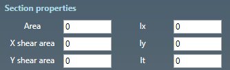
| Property | Unit Metric | Unit USA |
|---|---|---|
| Cross sectional area | mm² | in² |
| Shear area along X’ axis | mm² | in² |
| Shear area along Y’ axis | mm² | in² |
| Moment of inertia about X’ axis : Ix | mm^4 | in^4 |
| Moment of inertia about Y’ axis : Iy | mm^4 | in^4 |
| Torsional inertia : It | mm^4 | in^4 |
To know the UNIT of a property, just move the mouse over the property name.
- All other types :
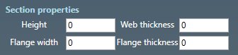
| Property | Unit Metric | Unit USA |
|---|---|---|
| Height | mm | in |
| Web thickness | mm | in |
| Flange width | mm | in |
| Flange thickness | mm | in |
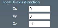
X-AXIS DIRECTION :
You can define the X-axis vector by defining Xx, Xy, Xz in global coordinates.
Use the left and right keyboard arrows to turn the X-axis vector 90°/-90°around the tangent direction.
LABEL :
You can define a label to this element. The labels are shown with the node names view button.

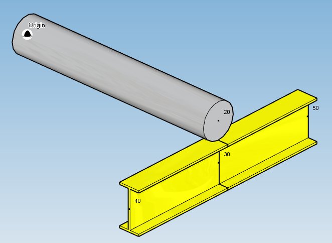
You can then define the second point of the beam thanks to the Orientation tool.
Click here for more information about the orientation tool.
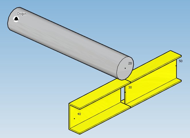
Create 2 I beams after creation of node 30 :
2. Modify/Remove a beam
Change the Selection mode to ELEMENT and select a beam :
Click here for more information about the selection tool.
You can change the type and the appropriate properties of the selected beam (except the length).
Click on the Modify button to change the selected beam with these new properties.
You can undo this command.
Click on the Remove button to delete the selected beam.
You can undo this command.
Example of modification, change I type to Channel type :
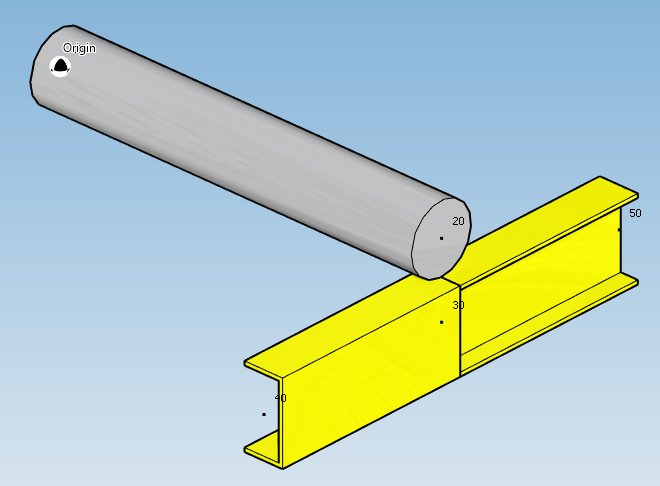
And by changing the X-axis direction :
3. Insert a beam on an intermediate node
Click on the Add beam button and select an intermediate node between 2 beams.
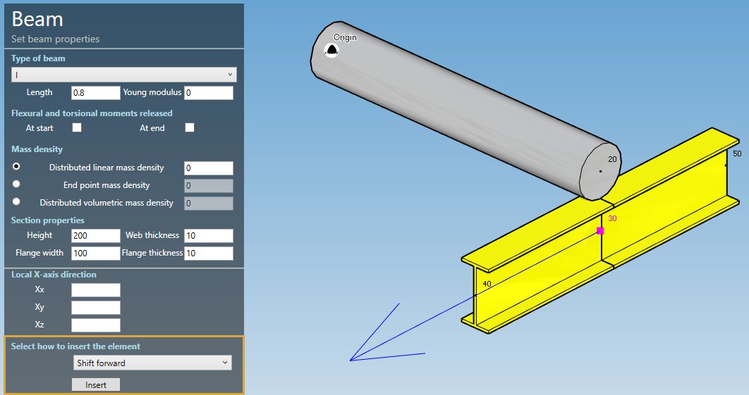
Fill the properties (see §1) and select the insertion mode :
- Shift forward
- Shift backwards
- Reduce the next element
- Reduce the previous element
- Symmetrically reduce the neighboring elements
ATTENTION, if the length is null, no mode will be proposed (empty list)
Based on the length of the beam and the lengths of the neighboring elements, some mode could be hidden.
Select for example “Shift forward” and click the Insert button :
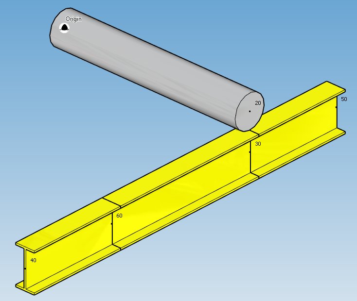
You can undo this command.