Create nodes
There are 3 possibilities of creation :
- Creation of the FIRST node
- Creation of a GLOBAL node
- Creation of a RELATIVE node
1. First node
The first node panel is called when a first beam needs a starting point.
Select a section and click on Draw structure, the Add node button is automatically selected :
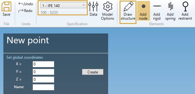
Set the GLOBAL X, Y, Z coordinates and a name.
See Global node just below :
2. Global node
If the selection is EMPTY, click on the Add node button to create a new global node.
You can Undo this command.
Fill the GLOBAL X, Y, Z coordinates and a name.
| Property | Description | Unit Metric | Unit USA |
|---|---|---|---|
| X | X global coordinate | m | ft |
| Y | Y global coordinate | m | ft |
| Z | Z global coordinate | m | ft |
| Name | Text or number | - | - |
To know the UNIT of the value, just let the mouse over the cell.
If Name is blank, the new node will receive an automatic name based on the Node settings.
Click here for more information about node naming.
3. Relative node
If a node is selected, you can create a new node relative to it in Global directions :
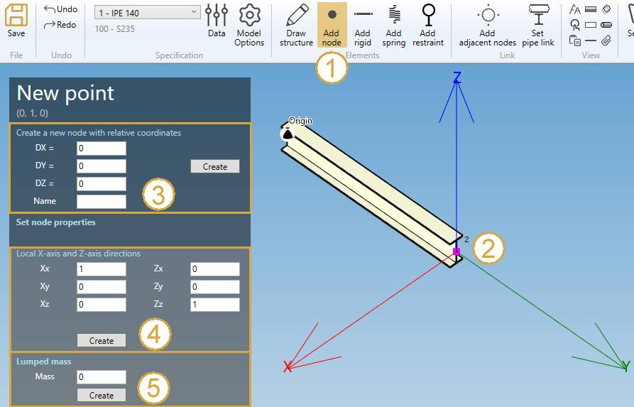
- Click on Add node button
- Select a node.
- Define the DX, DY, DZ, name of the new node.
- Click on Create
You can Undo this command.
Click here for more information about the selection tool.
| Property | Description | Unit Metric | Unit USA |
|---|---|---|---|
| DX | Relative distance from the selected node in X global direction | m | ft |
| DY | Relative distance from the selected node in Y global direction | m | ft |
| DZ | Relative distance from the selected node in Z global direction | m | ft |
| Name | Text or number | - | - |
If Name is blank, the new node will receive an automatic name based on the Node settings.
Click here for more information about node naming.
4. Creation of a local coordinate system
You can define a new local coordinate system on selected node (4).
- Click on Select point button
- Select a node
- Define the local coordinate system
- Click on Create
Just define the new X axis vector (Xx, Xy, Xz) in global coordinates and the new Z axis vector (Zx, Zy, Zz). The Y axis will be automatically defined.
By default, the local coordinate system is equal to the global coordinate system.
Example :
Change the X direction = axis of the beam and Z direction unchanged :
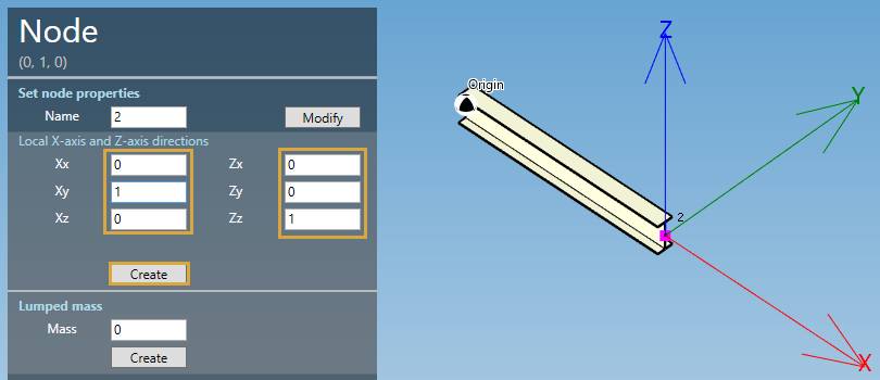
Click on Create button.
You can Undo this command.
5. Creation of a lumped mass
You can define a lumped mass on selected node (5) :
| Property | Unit Metric | Unit USA |
|---|---|---|
| Mass | ton | kips |
Click on the Create button to add a new lumped mass to the node.
You can later modify or remove this object by selecting this node and click on Modify/Remove buttons.
You can Undo this command.
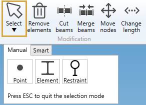
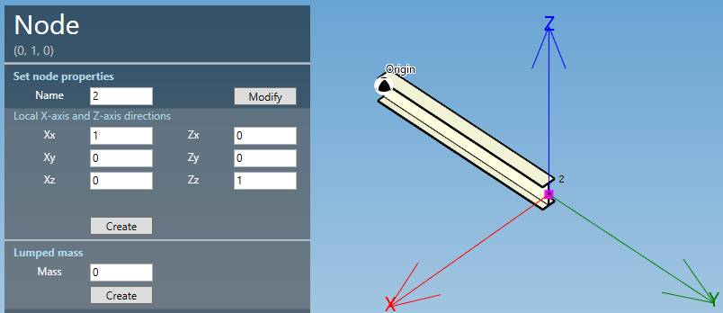
6. Modify a node
Change the Selection mode to POINT and select a node. Only the Name can be changed.
You can Undo this command.