Restraints
MetaPiping lets you create several types of restraints on nodes :
- Anchors
- Multiple restraints
- Rotational restraints
- Translational restraints
- Snubbers
- Variable spring hangers
- Constant spring hangers
- Non-linear restraints
1. Database
You can create Catalogs of restraints in the database :
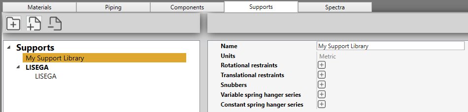
Click here to have more information about the support catalog creation.
2. Anchors
Select a Node and click on Add restraint button :

Select the type Anchor :
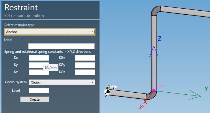
| Property | Description | Unit Metric | Unit USA |
|---|---|---|---|
| Label | Label of the restraint | - | - |
| Kx | Spring Constant acting in X direction | kN/mm | Kips/in |
| Ky | Spring Constant acting in Y direction | kN/mm | Kips/in |
| Kz | Spring Constant acting in Z direction | kN/mm | Kips/in |
| KΘx | Rotational Spring Constant acting in X direction | kN.m/rad | Kips.ft/rad |
| KΘy | Rotational Spring Constant acting in Y direction | kN.m/rad | Kips.ft/rad |
| KΘz | Rotational Spring Constant acting in Z direction | kN.m/rad | Kips.ft/rad |
To know the UNIT of the value, just move the mouse over the cell.
The labels are shown with the node names view button.
You can change the coordinate system that defines the directions X,Y,Z :
- Global (default)
- Local to adjacent element
The Level is used to identify the spectrum applied to this anchor for multilevel floor response spectrum analysis.
You can later modify or remove this anchor by selecting it and clicking on Modify/Remove buttons.
You can Undo this command.
3. Multiple restraints
Select a Node and click on Add restraint button :
Select the type Multiple restraint :
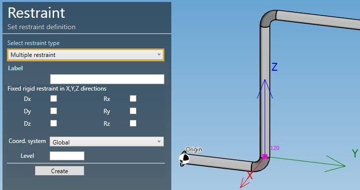
| Property | Description |
|---|---|
| Label | Label of the restraint |
| Dx | Checked if there is a fixed rigid restraint acting in X direction |
| Dy | Checked if there is a fixed rigid restraint acting in Y direction |
| Dz | Checked if there is a fixed rigid restraint acting in Z direction |
| Rx | Checked if there is a fixed rigid rotational restraint about X axis |
| Ry | Checked if there is a fixed rigid rotational restraint about Y axis |
| Rz | Checked if there is a fixed rigid rotational restraint about Z axis |
The labels are shown with the node names view button.
You can change the coordinate system that defines the directions X,Y,Z :
- Global (default)
- Local to adjacent element
The Level is used to identify the spectrum applied to this restraint for multilevel floor response spectrum analysis.
You can later modify or remove this restraint by selecting it and clicking on Modify/Remove buttons.
You can Undo this command.
4. Rotational restraints
Select a Node and click on Add restraint button :
Select the type Rotational restraint :
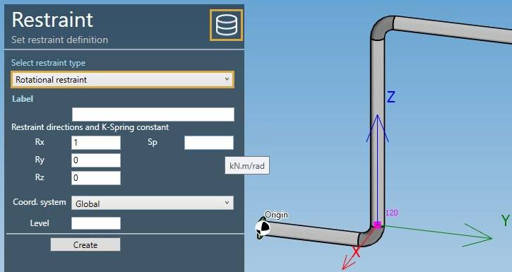
| Property | Description | Unit Metric | Unit USA |
|---|---|---|---|
| Label | Label of the restraint | - | - |
| Rx | X direction of the restraint | - | - |
| Ry | Y direction of the restraint | - | - |
| Rz | Z direction of the restraint | - | - |
| Sp | Rotational Spring Constant | kN.m/rad | Kips.ft/rad |
if Sp is blank = rigid, which is modeled by using a value of 1.13 x 10^9 kN.m/rad or 8.33 x 10^8 Kips.ft/rad.
To know the UNIT of the value, just move the mouse over the cell.
The labels are shown with the node names view button.
The Database button on upper right corner gives an access to the libraries :
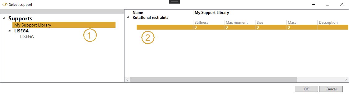
Select a library on the left treeview, then select a row that represents a predefined restraint. Some values are just informative. Click OK. The properties are copied to the restraint screen.
You can change the coordinate system that defines the directions X,Y,Z :
- Global (default)
- Local to adjacent element
The Level is used to identify the spectrum applied to this restraint for multilevel floor response spectrum analysis.
You can later modify or remove this restraint by selecting it and clicking on Modify/Remove buttons.
You can Undo this command.
5. Translational restraints
Select a Node and click on Add restraint button :
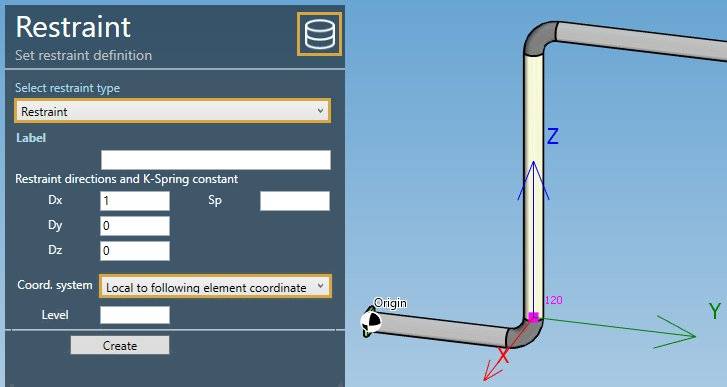
Select the type Restraint :
| Property | Description | Unit Metric | Unit USA |
|---|---|---|---|
| Label | Label of the restraint | - | - |
| Dx | X direction of the restraint | - | - |
| Dy | Y direction of the restraint | - | - |
| Dz | Z direction of the restraint | - | - |
| Sp | Translational Spring Constant | kN/mm | Kips/in |
if Sp is blank = rigid, which is modeled by using a value of 8.75 x 10^5 N/mm or 5 x 10^6 lb/in.
To know the UNIT of the value, just move the mouse over the cell.
The labels are shown with the node names view button.
The Database button on upper right corner gives an access to the libraries.
You can change the coordinate system that defines the directions X,Y,Z :
- Global (default)
- Local to adjacent element (in yellow in the picture)
The Level is used to identify the spectrum applied to this restraint for multilevel floor response spectrum analysis.
You can later modify or remove this restraint by selecting it and clicking on Modify/Remove buttons.
You can Undo this command.
6. Snubbers
Select a Node and click on Add restraint button :
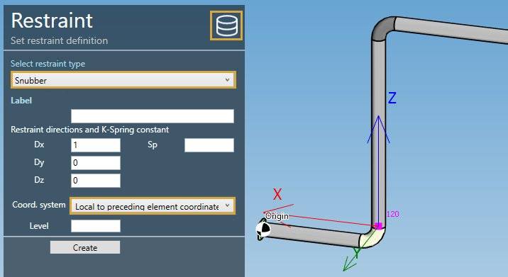
Select the type Snubber :
| Property | Description | Unit Metric | Unit USA |
|---|---|---|---|
| Label | Label of the restraint | - | - |
| Dx | X direction of the restraint | - | - |
| Dy | Y direction of the restraint | - | - |
| Dz | Z direction of the restraint | - | - |
| Sp | Translational Spring Constant | kN/mm | Kips/in |
if Sp is blank = rigid, which is modeled by using a value of 2.625 x 10^5 N/mm or 1.5 x 10^6 lb/in.
To know the UNIT of the value, just move the mouse over the cell.
The labels are shown with the node names view button.
The Database button on upper right corner gives an access to the libraries.
You can change the coordinate system that defines the directions X,Y,Z :
- Global (default)
- Local to adjacent element (in yellow in the picture)
The Level is used to identify the spectrum applied to this restraint for multilevel floor response spectrum analysis.
You can later modify or remove this restraint by selecting it and clicking on Modify/Remove buttons.
You can Undo this command.
7. Variable spring hangers
Select a Node and click on Add restraint button :
Select the type Variable support spring hanger :
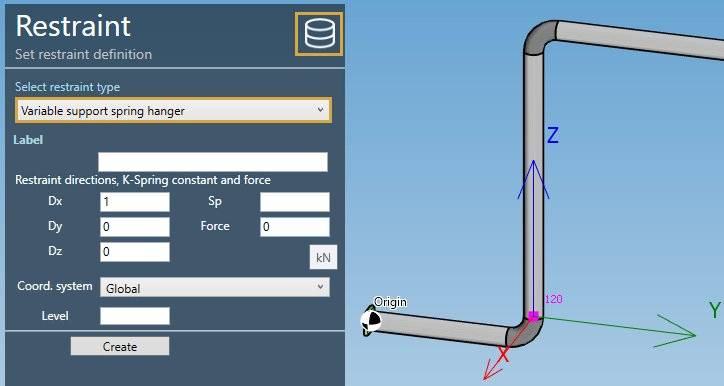
| Property | Description | Unit Metric | Unit USA |
|---|---|---|---|
| Label | Label of the restraint | - | - |
| Dx | X direction of the restraint | - | - |
| Dy | Y direction of the restraint | - | - |
| Dz | Z direction of the restraint | - | - |
| Sp | Spring Constant | kN/mm | Kips/in |
| Force | Pre-compression/pre-tension force | kN | Kips |
if Sp is blank = rigid, which is modeled by using a value of 8.75 x 10^5 N/mm or 5 x 10^6 lb/in.
To know the UNIT of the value, just move the mouse over the cell.
The labels are shown with the node names view button.
The Database button on upper right corner gives an access to the libraries.
You can change the coordinate system that defines the directions X,Y,Z :
- Global (default)
- Local to adjacent element
The Level is used to identify the spectrum applied to this restraint for multilevel floor response spectrum analysis.
You can later modify or remove this rstraint by selecting it and clicking on Modify/Remove buttons.
You can Undo this command.
8. Constant spring hangers
Select a Node and click on Add restraint button :
Select the type Constant support hanger :
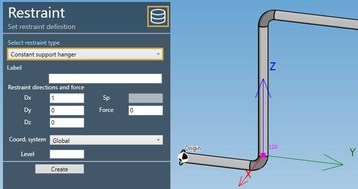
| Property | Description | Unit Metric | Unit USA |
|---|---|---|---|
| Label | Label of the restraint | - | - |
| Dx | X direction of the restraint | - | - |
| Dy | Y direction of the restraint | - | - |
| Dz | Z direction of the restraint | - | - |
| Force | Pre-compression/pre-tension force | kN | Kips |
To know the UNIT of the value, just move the mouse over the cell.
The labels are shown with the node names view button.
The Database button on upper right corner gives an access to the libraries.
You can change the coordinate system that defines the directions X,Y,Z :
- Global (default)
- Local to adjacent element
The Level is used to identify the spectrum applied to this restraint for multilevel floor response spectrum analysis.
You can later modify or remove this restraint by selecting it and clicking on Modify/Remove buttons.
You can Undo this command.
9. Non-linear restraint
Select a Node and click on Add restraint button :
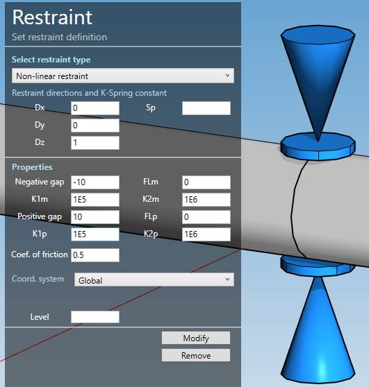
Select the type Non-linear restraint :
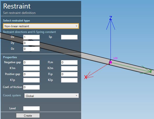
| Property | Description | Unit Metric | Unit USA |
|---|---|---|---|
| Label | Label of the restraint | - | - |
| Dx | X direction of the restraint | - | - |
| Dy | Y direction of the restraint | - | - |
| Dz | Z direction of the restraint | - | - |
| Sp | Translational Spring Constant | kN/mm | Kips/in |
if Sp is blank = rigid, which is modeled by using a value of 8.75 x 10^5 N/mm or 5 x 10^6 lb/in.
To know the UNIT of the value, just move the mouse over the cell.
The labels are shown with the node names view button.
| Property | Description | Unit Metric | Unit USA |
|---|---|---|---|
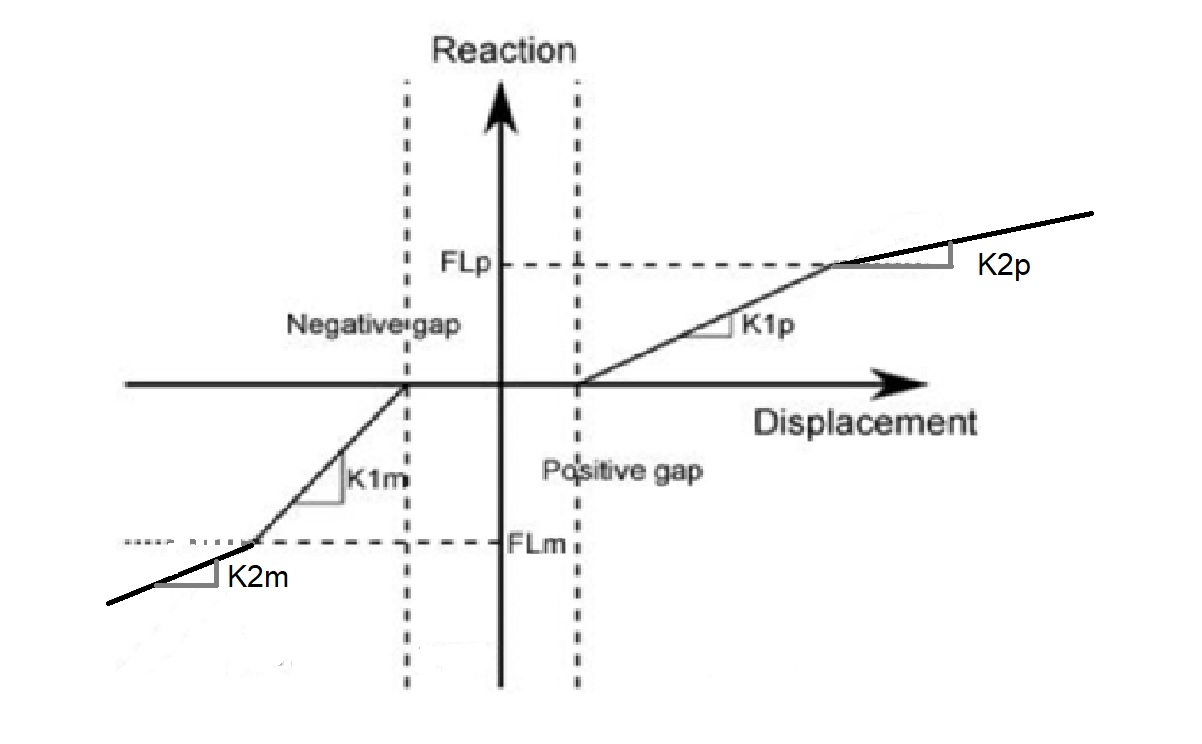
| Negative gap | Must be ≤ 0 | mm | in |
| K1m | First spring constant in the negative direction | kN/mm | Kips/in |
| K2m | Second spring constant in the negative direction | kN/mm | Kips/in |
| Positive gap | Must be ≥ 0 | mm | in |
| K1p | First spring constant in the positive direction | kN/mm | Kips/in |
| K2p | Second spring constant in the positive direction | kN/mm | Kips/in |
| FLm | Reaction at stiffness transition from K1m to K2m (≤ 0, infinite if blank or 0) | kN | Kips |
| FLp | Reaction at stiffness transition from K1p to K2p (≥ 0, infinite if blank or 0) | kN | Kips |
| Coef. of friction | Coulomb coefficient of friction between the pipe and the support (≥ 0) | - | - |
You can change the coordinate system that defines the directions X,Y,Z :
- Global (default)
- Local to adjacent element
The Level is used to identify the spectrum applied to this restraint for multilevel floor response spectrum analysis.
You can later modify or remove this restraint by selecting it and clicking on Modify/Remove buttons.
You can Undo this command.
Example :