Create rigids
A rigid is a straight element sufficiently stiff to rigidly transmit all deflections and rotations.
When you click on the Add rigid button without selection, the left panel shows a message :
Select 1 node
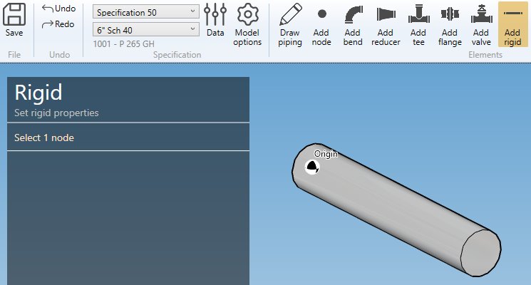
The selection mode is automatically set to POINT. You can so directly select a node.
1. Create a rigid
- Select a node.
- Click the Add rigid button.
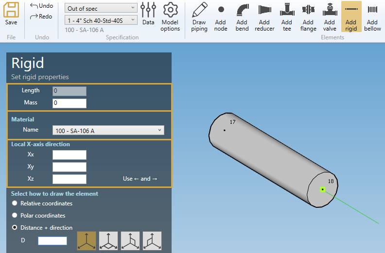
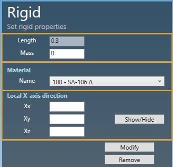
RIGID PROPERTIES :
| Property | Unit Metric | Unit USA |
|---|---|---|
| Length | m | ft |
| Mass | ton | kips |
The length must be defined by the orientation tool.
MATERIAL :
Select the material of the rigid.
Click here for more information about the materials definition.
X-AXIS DIRECTION :
You can define the X-axis vector by defining Xx, Xy, Xz in global coordinates.
Use the left and right keyboard arrows to turn the X-axis vector 90°/-90°around the tangent direction.
LABEL :
You can define a label to this element. The labels are shown with the node names view button.

NEXT NODE :
You can set the next extremity node name of the element. If blank, the software will define it automatically. The software will also check that the name doesn’t already exist.
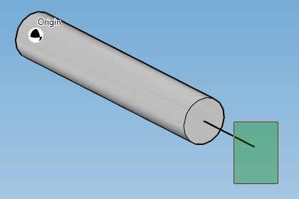
You can then define the second point of the rigid thanks to the Orientation tool.
Click here for more information about the orientation tool.
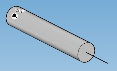
Create the rigid (represented by a black line) :
2. Modify/Remove a rigid
Change the Selection mode to ELEMENT and select a rigid by dragging a selection rectangle :
Click here for more information about the selection tool.
You can change the properties of the selected rigid (except the length).
MATERIAL :
Change the material of the rigid.
X-AXIS DIRECTION :
You can change the X-axis vector by defining Xx, Xy, Xz in global coordinates.
Click on the Modify button to change the selected rigid with these new properties.
You can undo this command.
Click on the Remove button to delete the selected rigid.
You can undo this command.
3. Insert a rigid on an intermediate node
Click on the Add rigid button and select an intermediate node between 2 elements.

Fill the properties (see §1) and select the insertion mode :
- Shift forward
- Shift backwards
- Reduce the next element
- Reduce the previous element
- Symmetrically reduce the neighboring elements
ATTENTION, if the length is null, no mode will be proposed (empty list)
Based on the length of the rigid and the lengths of the neighboring elements, some mode could be hidden.
Select for example “Reduce the next element” and click the Insert button :

You can undo this command.