Create reducers
When you click on the Add reducer button without selection, the left panel shows a message :
Select 1 extremity node
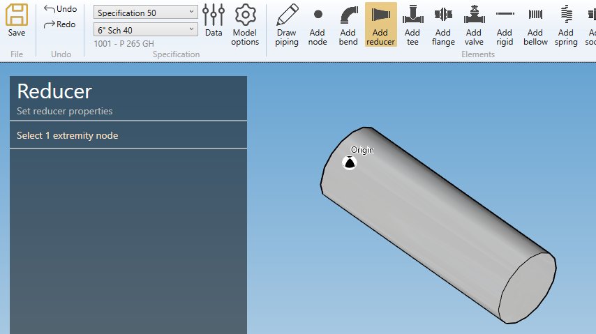
The selection mode is automatically set to POINT. You can so directly select a node.
ATTENTION, you cannot start a reducer from an isolated node, only from the extremity of an element. If you have to start your piping line by a reducer, first create a small pipe in opposite direction, create a reducer from an extremity, then remove the pipe.
1. Create a reducer from another element
- Select the current section/material in the specification box (1).
- Select a node (2).
- Click the Add reducer button
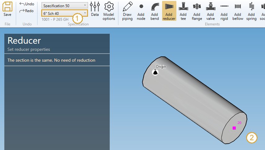
If the section of the element on node has the same section than the current specification (1), the left panel shows a message :
The section is the same. No need of reduction
If the section of the element on node is different from the current specification (Ex : 4” Sch 40), you can define a new reducer :
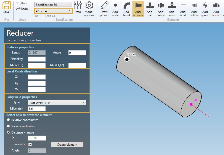
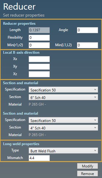
REDUCER PROPERTIES :
Define the properties of the new reducer :
| Property | Unit Metric | Unit USA | Remark |
|---|---|---|---|
| Length | m | ft | |
| Angle | ° | ° | |
| Flexibility | - | - | |
| Min(r1,r2) | mm | in | Minimum radius r1,r2 : B31J, Class 1 and Classes 2 & 3 Revision A94 for C2 of equations X and Z |
| Min(L1,L2) | m | ft | Minimum tangent L1, L2 : for B31J and Class 1 only |
The Length and Angle come from the current specification :
You can change the flexibility factor of the reducer. If blank, default value = 1.
X-AXIS DIRECTION :
You can change the X-axis vector by defining Xx, Xy, Xz in global coordinates.
Use the left and right keyboard arrows to turn the X-axis vector 90°/-90°around the tangent direction.
LABEL :
You can define a label to this element. The labels are shown with the node names view button.
LONG WELD :
You can change the Long weld properties :
For the type, you can choose between :
- None
- Butt weld flush
- Butt weld as welded
Based on this property, define the Long weld mismatch [mm or in].
In this example, the default values correspond to the first section preset.
NEXT NODE :
You can set the next extremity node name of the element. If blank, the software will define it automatically. The software will also check that the name doesn’t already exist.
You can then define the second point of the reducer thanks to the Orientation tool.
Click here for more information about the orientation tool.
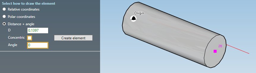
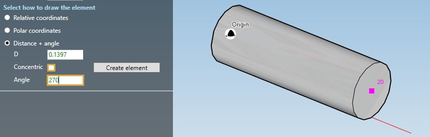
By default, the Distance + angle tool is activated with the default length and in concentric mode :
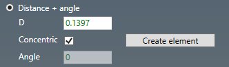
| Property | Unit Metric | Unit USA |
|---|---|---|
| D | m | ft |
| Angle | ° | ° |
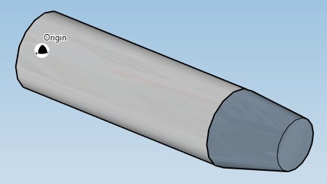
A red line shows a preview of the second point of the reducer :
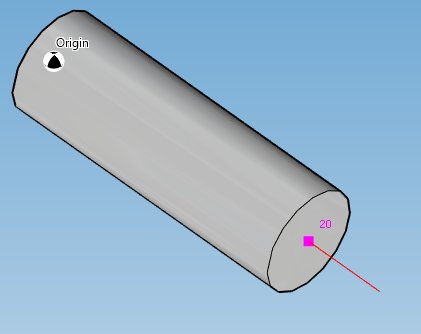
ATTENTION, you can change the length of the reducer but it will no more be standard
You can click on the Create element to create a concentric reducer :
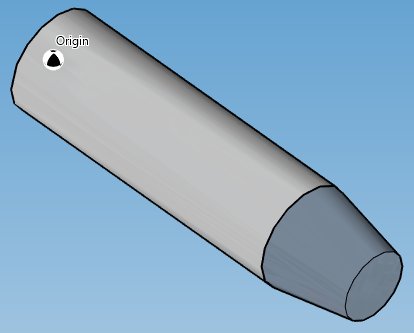
You can undo this command.
ECCENTRIC REDUCER :
Check the Eccentric checkbox and define at which side of the pipe you want to be tangent (thanks to the Angle property) :
A red line shows a preview of the tangent side and length of the reducer.
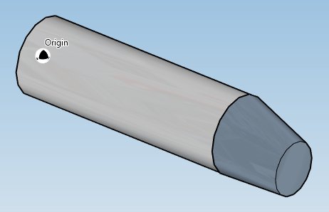
You can click on the Create element to create a right aligned eccentric reducer :
You can undo this command.
Another example with Angle = 270 ° :
You can click on the Create element to create a bottom aligned eccentric reducer :
You can undo this command.
2. Modify/Remove a reducer
Change the Selection mode to ELEMENT and select a reducer :
Click here for more information about the selection tool.
REDUCER PROPERTIES :
You can change the properties of the selected reducer (except the length) :
| Property | Unit Metric | Unit USA | Remark |
|---|---|---|---|
| Length | m | ft | |
| Angle | ° | ° | |
| Flexibility | - | - | |
| Min(r1,r2) | mm | in | Minimum radius r1,r2 : B31J, Class 1 and Classes 2 & 3 Revision A94 for C2 of equations X and Z |
| Min(L1,L2) | m | ft | Minimum tangent L1, L2 : for B31J, Class 1 only |
You can change the flexibility factor of the reducer. If blank, default value = 1.
X-AXIS DIRECTION :
You can change the X-axis vector by defining Xx, Xy, Xz in global coordinates.
LABEL :
You can change the label of the element.
SECTION AND MATERIAL :
You can change the specification and section/material of the two extremities of the reducer.
LONG WELD :
You can change the Long weld properties :
For the type, you can choose between :
- None
- Butt weld flush
- Butt weld as welded
Based on this property, define the Long weld mismatch [mm or in].
In this example, the default values correspond to the first section preset.
Click on the Modify button to change the selected reducer with these new properties.
You can undo this command.
Click on the Remove button to delete the selected reducer.
You can undo this command.