Spring
When you click on the Add spring button without selection, the left panel shows a message :
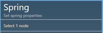
The selection mode is automatically set to POINT. You can so directly select a node.
1. Create a spring
- Select a node.
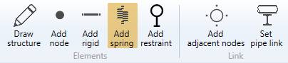
- Click the Add spring button.
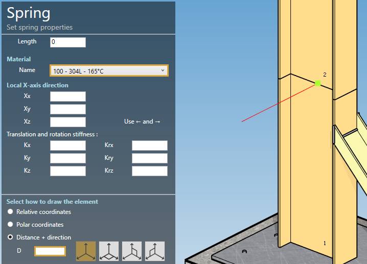
The length must be defined by the orientation tool.
Click here for more information about the orientation tool.
Set the default material of the spring.
You can define the Local X-axis vector by defining Xx, Xy, Xz in global coordinates.
Stiffnesses :
| Property | Description | Unit Metric | Unit USA |
|---|---|---|---|
| Length | - | m | ft |
| Kx | Translation stiffness in X direction | kN/mm | kips/in |
| Kx | Translation stiffness in Y direction | kN/mm | kips/in |
| Kx | Translation stiffness in Z direction | kN/mm | kips/in |
| Krx | Rotation stiffness in X direction | kN.m/rad | kips.ft/rad |
| Kry | Rotation stiffness in Y direction | kN.m/rad | kips.ft/rad |
| Krz | Rotation stiffness in Z direction | kN.m/rad | kips.ft/rad |
Blank values mean that the corresponding degrees of freedom are blocked.
You can then define the second point of the spring thanks to the Orientation tool.
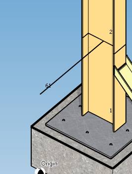
Create the spring (represented by a black line) :
You can undo this command.
2. Modify/Remove a spring
Select a spring, change some properties and click on the Modify button or delete it by clicking the Remove button.
You can undo this command.