Rigid
A rigid is a straight element sufficiently stiff to rigidly transmit all deflections and rotations.
When you click on the Add rigid button without selection, the left panel shows a message :
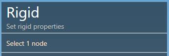
The selection mode is automatically set to POINT. You can so directly select a node.
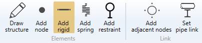
1. Create a rigid
- Select a node.
- Click the Add rigid button.
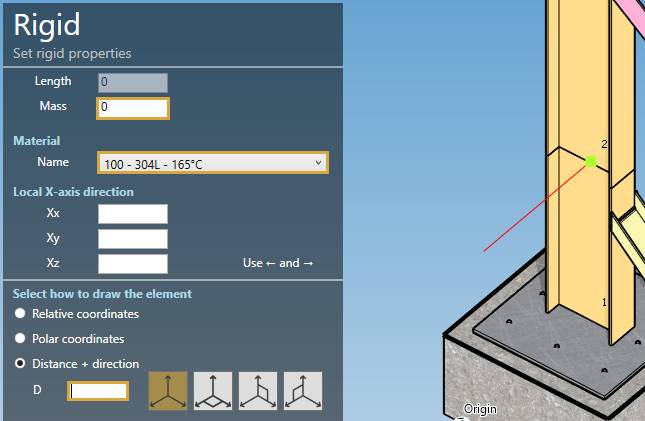
| Property | Unit Metric | Unit USA |
|---|---|---|
| Length | m | ft |
| Mass | ton | kips |
The length must be defined by the orientation tool.
Click here for more information about the orientation tool.
Set the default material of the rigid.
You can define the Local X-axis vector by defining Xx, Xy, Xz in global coordinates.
You can then define the second point of the rigid thanks to the Orientation tool.
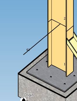
Create the rigid (represented by a black line) :
You can undo this command.
2. Modify/Remove a rigid
A rigid can also be used to simulate an eccentricity between beams.
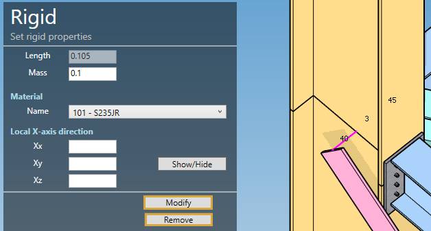
Select a rigid, change some properties and click on the Modify button or delete it by clicking the Remove button.
You can undo this command.