Stress combination cases
This case consists of combining the results of load cases, dynamic cases or previously calculated
combination cases to form a new case and of calculating additive stresses which are based on the
resultant moments of the constituent cases.
ATTENTION, this case may be used for all piping codes except ASME Class 1, RCC-M Class 1 and ASME HDPE Codes.
Click here for more information about the piping codes.
When selecting Stress combination cases, all existing stress combinations are listed in the combobox :
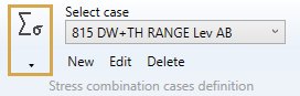
The loads appear with their Case number + Title.
1. General
When editing, the definition window shows up :
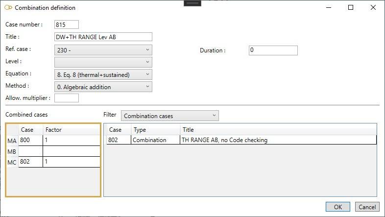
Enter a Case number and a Title.
Ref. case :
Operating pressures (and allowable stresses) of the reference case will be used for this case. The calculation of allowable stresses depends on the current calculation code.
Click here for more information about all possible codes.
Level :
This field is intended for nuclear piping codes only. The possible values are : A (normal conditions), B (upset), C (emergency), D (faulted) and T (test).
Equation :
The equations are code-dependent.
Method :
- 0- Algebraic addition
- 1- Absolute addition
- 2- SRSS
- 3- Seismic
- 4- Maximum absolute
- 5- Maximum resultant
- 6- Algebraic maximum
- 7- Algebraic minimum
- 8- Range
- 9- Max resultant moment range
- S- Max thermal stress range
Allowable multiplier f :
If this field is not blank and different from 0, then the allowable stress for this case will be f * Sh.
Duration :
This field (expressed in hours) is used for RCC-MRx code only. It allows to calculate the creep effects. If not entered or 0, the duration entered in the reference case is used.
2. Combined cases
Enter the number of the constituent cases and the corresponding factor.
MA = Sustained load case
MB = Occasional load case
MC = Thermal load case
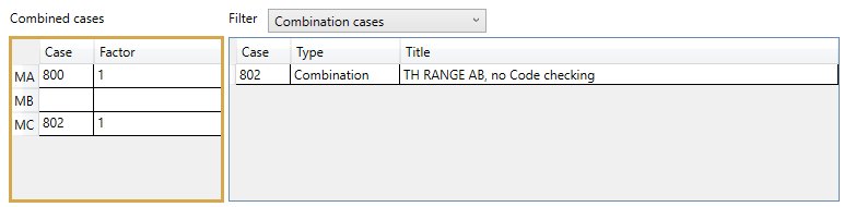
On right side, as a reminder, the list of all cases. You can filter them by selecting the type :
- All
- Static
- Dynamic
- Combination