Reporting
MetaPiping and MetaStructure can generate reports with all the details of the model input, some review pictures and all results of an analysis.
The report is exclusively based on *.docx file.
ATTENTION, it is mandatory that Microsoft Word must be installed on user computer !
A report is based on an empty template (*.docx) that contains keywords.
A keyword is associated to a section described in a table document (*.docx).
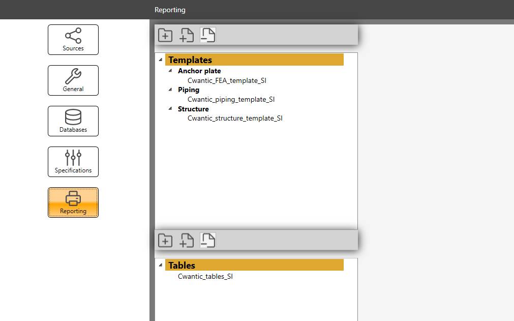
User can prepare template document and table document and then import them in the software (the first one in the template section, the second in the table section) as shown in the upper figure.
Select a document shows a preview on the right panel.
ATTENTION, the documents are copied in the settings. The original word files are not moved nor modified.
1. Keyword mechanism
The keyword is useful to make a correspondence between the template and the table document but with specific decorators :
$$keyword$$ for the template
[keyword] for the table
Example :
| Keyword | Template keyword | Table keyword |
|---|---|---|
| MATERIALS | $$MATERIALS$$ | [MATERIALS] |
A digit is authorized after a keyword [0..9] to enlarge the possibilities.
Example :
| Keyword | Template keyword | Table keyword |
|---|---|---|
| MATERIALS | $$MATERIALS0$$ -> $$MATERIALS9$$ | [MATERIALS0] -> [MATERIALS9] |
If the software encounters the keyword $$MATERIALS3$$ in the template, it will know that it corresponds to the internal keyword MATERIALS and will try to find the section in the table document with the keyword [MATERIAL3]. If succeed, it will insert the content of the table at the position of the template keyword and fill all materials.
ATTENTION, the keyword must be written in CAPITAL letters.
2. Template
A template is a Word *.docx file with user defined layout and content.
MetaPiping/MetaStructure let you insert datas from the current study inside the template at a certain position in the document via keywords.
2.2 Keywords
| Keyword | Module(s) | Description | Other possible keyword or remark |
|---|---|---|---|
| STUDY NAME | MetaPiping/MetaStructure/Finite element analysis | The name of the current study | No table |
| PICTURE | MetaPiping/MetaStructure/Finite element analysis | Take a picture (§2.3) | No table |
| SECTIONS | MetaPiping/MetaStructure | The list of all sections | CROSS SECTION |
| MATERIALS | MetaPiping/MetaStructure | The list of all materials | |
| NODES | MetaPiping/MetaStructure | The list of all nodes | NODES INPUT |
| ELEMENTS | MetaPiping/MetaStructure | The list of all elements | ELEMENTS INPUT |
| ELEMENT COORDINATE SYSTEMS | MetaPiping/MetaStructure | The list of all elements with non default CS | |
| NODE COORDINATE SYSTEMS | MetaPiping/MetaStructure | The list of all DLCS | |
| LUMPED MASSES | MetaPiping/MetaStructure | The list of all lumped masses | |
| SUPPORTS | MetaPiping/MetaStructure | The list of all restraints | SUPPORT |
| STATIC CASES | MetaPiping/MetaStructure | The list of all static cases | |
| EXTERNAL CASES | MetaStructure | The list of all external cases | from linked studies |
| FORCES | MetaPiping/MetaStructure | The list of all nodal load forces | also the external forces (linked study) |
| MOVEMENTS | MetaPiping/MetaStructure | The list of all restraint movements | DISPLACEMENTS |
| OPERATING CONDITIONS | MetaPiping/MetaStructure | The list of all operating conditions | TEMPERATURE & PRESSURE |
| DISTRIBUTED FORCES | MetaPiping/MetaStructure | The list of all distributed forces | |
| WIND | MetaPiping/MetaStructure | The list of all wind forces | |
| SNOW | MetaPiping/MetaStructure | The list of all snow forces | |
| ACCELERATIONS | MetaPiping/MetaStructure | The list of all static accelerations | |
| DENSITIES | MetaPiping | The list of all content densities | |
| STRATIFICATIONS | MetaPiping | The list of all stratifications | |
| COLD SPRINGS | MetaPiping | The list of all cold springs | |
| TRANSIENTS | MetaPiping | The list of all transients | |
| LOAD SETS | MetaPiping | The list of all load sets | |
| SPECTRA | MetaPiping/MetaStructure | The list of all spectra | |
| DYNAMIC EVENTS | MetaPiping/MetaStructure | The list of all dynamic node loads | |
| DYNAMIC CASES | MetaPiping/MetaStructure | The list of all dynamic cases | |
| PRIMARY RESPONSE | MetaPiping/MetaStructure | The list of all primary cases | |
| SECONDARY RESPONSE | MetaPiping/MetaStructure | The list of all secondary cases | |
| COMBINATION CASES | MetaPiping/MetaStructure | The list of all combination cases | |
| COMBINED STRESS CASES | MetaPiping | The list of all combined stress cases | |
| RDISPLACEMENTS | MetaPiping/MetaStructure | The list of all displacement results | Possible JSON parameters (see §3) |
| RFORCES | MetaPiping/MetaStructure | The list of all force and moment results | Possible JSON parameters (see §3) |
| REACTIONS | MetaPiping/MetaStructure | The list of all reaction results | Possible JSON parameters (see §3) |
| STRESSES | MetaPiping/MetaStructure | The list of all stress results | Possible JSON parameters (see §3) |
| FILE | MetaPiping/MetaStructure | A file content | Mandatory JSON parameters (see §3.1) |
| ANCHOR PLATES | MetaStructure | The list of all anchor plate results | |
| JOINTS | MetaStructure | The list of all joint results | |
| ANCHORS RESULTS | Finite element analysis | The list of all fastener results | |
| MESH RESULTS | Finite element analysis | The list of all mesh results | |
| ANALYSIS NAME | Finite element analysis | The name of the current analysis | No table |
| CONFIGURATION NAME | Finite element analysis | The name of the current configuration | No table |
| HEIGHT | Finite element analysis | The height of the current assembly | No table |
| MESH SIZE | Finite element analysis | The meshing size | No table |
| IDNODE | Finite element analysis | The name of the current node | No table |
| LOADCASE | Finite element analysis | The current load case | No table |
| STATIC EQUILIBRIUM | Finite element analysis | The static equilibrium value | No table |
| DISPLACEMENT MAX | Finite element analysis | The displacement max | No table |
| STRESS MAX | Finite element analysis | The stress max | No table |
| ALLOWABLE STRESS | Finite element analysis | The allowable stress of material | No table |
| STRAIN MAX | Finite element analysis | The strain max | No table |
| COMPRESSION MAX | Finite element analysis | The compression max on concrete | No table |
| FASTENER RATIO MAX | Finite element analysis | The max ratio on all fasteners | No table |
2.3 Pictures
It is possible to include pictures in the report with use of the keyword PICTURE.
When the software encounters this keyword, it simply makes a screenshot of the 3D engine.
It is possible to change the kind of visualization via a JSON structure just after the keyword separated by a semicolon character :
$$PICTURE;{...}$$
2.3.1 Piping & structure parameters
JSON parameters :
| Parameter | Description | Default value |
|---|---|---|
| Layers | An array of visible layer name | Empty list = all layers will be visible |
| View | Orientation of the camera | 39 (= FrontFaceTopLeft - see below) |
| Mode | Display mode | 0 (= Shaded - see below) |
| Type | Ribbon type | 0 (= Conception - see below) |
| ReviewType | Review category | 0 (= Sections - see below) |
| ResultType | Result category | 0 (= Displacements - see below) |
| LoadCase | Index of mode (+1) or load case in the list | -99 (see below ) |
| Factor | Amplification factor of the displacements | 1 |
| StressIndex | Index in possible stress list | 0 |
| StressMax | 1 = show the max stress colorisation | 0 |
| ShowNodes | 1 = show node point and name | 0 (see below ) |
| ShowOrigin | 1 = show origin | 0 |
| ShowAxis | 1 = show axis | 0 |
No parameter is mandatory. If a parameter is not specified, its default value will be used.
View values :
    Front                   = 0
    Right                   = 1
    Rear                    = 2
    Left                    = 3
    Top                     = 4
    Bottom                  = 5
    Isometric               = 6
    Dimetric                = 7
    FrontFaceLeft           = 12
    RightFaceBottom         = 13
    RightFaceRight          = 14
    RightFaceTop            = 15
    RightFaceLeft           = 16
    BackFaceBottom          = 17
    BackFaceRight           = 18
    BackFaceTop             = 19
    BackFaceLeft            = 20
    LeftFaceBottom          = 21
    LeftFaceRight           = 22
    LeftFaceTop             = 23
    LeftFaceLeft            = 24
    BottomFaceBottom        = 25
    BottomFaceRight         = 26
    BottomFaceTop           = 27
    BottomFaceLeft          = 28
    TopFaceBottom           = 29
    TopFaceRight            = 30
    TopFaceTop              = 31
    TopFaceLeft             = 32
    FrontFaceBottomLeft     = 33
    FrontFaceBottomRight    = 34
    FrontFaceTopLeft        = 35
    FrontFaceTopRight       = 36
    BackFaceBottomLeft      = 37
    BackFaceBottomRight     = 38
    BackFaceTopLeft         = 39
    BackFaceTopRight        = 40
Mode values :
    Shaded = 0
    Hiddenlines = 1
    Iso = 2
Type values :
    Conception  = 0
    Loads       = 10
    Review      = 20
    Analysis    = 30
Review type values :
    Sections = 0
    Materials = 10
    Specifications = 20
    StressOff = 30
    Soils = 40
    Codes = 50
    RoomTemperatures = 60
    DesignConditions = 70
    EndConditions = 80
Result type values :
    None = -1
    Displacements = 0
    Reactions = 1
    Forces = 2
    RestraintForces = 3
    Stresses = 4
    Anchors = 5
    Joints = 6
LoadCase values :
    None : -99
    Mode : 1 --> all frequencies < 100 (only for displacements)
    Case : >= 100
    Fatigue : 0
    Creep : -1
ShowNodes values :
    None : 0
    All : 1
    Only restrained nodes : 2
    Only tee nodes : 3 (only for piping)
Examples:
$$PICTURE$$
$$PICTURE;{“View”:35}$$
$$PICTURE;{”Type”:20,”ReviewType“:10,“View”:35}$$
$$PICTURE;{”Type”:30,”ResultType“:0,”Layers”:[“0”],”LoadCase”:100,“View”:35,”Factor”:8}$$
2.3.2 Finite element analysis parameters
JSON parameters :
| Parameter | Description | Default value |
|---|---|---|
| Groups | An array of visible group name | Empty list = all groups will be visible |
| View | Orientation of the camera | 35 (= FrontFaceTopLeft - see above) |
| ResultType | Result category | 0 (= Group - see below) |
| Factor | Amplification factor of the displacements | 1 |
| Dim | 1 = show dimensions | 1 |
Result type values :
    Group = 0
    Displacement = 1
    Stress = 2
    Strain = 3
    Compression = 4
    IsoDisplacement = 5
    IsoStress = 6
    IsoStrain = 7
    IsoCompression = 8
Examples:
$$PICTURE$$
$$PICTURE;{“ResultType”:2,”Groups”:[“PLATE”],”View”:4,”Dim”:0}$$
3. Results params
For results keywords, it is possible to filter the output via a JSON structure just after the keyword separated by a semicolon character :
$$RDISPLACEMENTS;{...}$$
$$RFORCES;{...}$$
$$REACTIONS;{...}$$
$$STRESSES;{...}$$
JSON parameters :
| Parameter | Description | Default value |
|---|---|---|
| Layers | An array of visible layer name | Empty list = all layers will be visible |
| LoadCase | A loadcase number | -99 (all loadcases) |
| StressIndex | A stress index | 0 (for stress results only) |
| NMax | Show only the NMax number of the higher results for each loadcases | 0 (all results) |
LoadCase values :
    All : -99
    Mode : 1 --> all frequencies < 100 (only for displacements)
    Case : >= 100
    Fatigue : 0
    Creep : -1
Examples:
$$RDISPLACEMENTS$$
This will show a table with all displacements (all layers) for all loadcases.
$$RDISPLACEMENTS;{”Layers”:[“0”,"1"],”LoadCase”:100,”NMax”:5}$$
This will show a table with the 5 highest displacements of nodes from layer “0” and “1” and only for loadcase 100.
You can combine in your report a picture and a result table :
FORCES & MOMENTS:
-----------------

1) Loadcase 100 - layer 0

        $$PICTURE;{”Type”:30,”ResultType“:2,”Layers”:[“0”],”LoadCase”:100,“View”:35}$$

$$RFORCES;{”Layers”:[“0”],”LoadCase”:100}$$
This will first show a PICTURE (see §2.3.1) :
| Parameter | Description |
|---|---|
| ”Type”:30 | Analysis screen |
| ”ResultType“:2 | Forces |
| ”Layers”:[“0”] | Only elements of layer “0” |
| ”LoadCase”:100 | Only for loadcase number 100 |
| “View”:35 | FrontFaceTopLeft view |
…followed by a table :
| Parameter | Description |
|---|---|
| ”Layers”:[“0”] | Only results of elements of layer “0” |
| ”LoadCase”:100 | Only for loadcase number 100 |
3.1 File param
$$FILE;{...}$$
Mandatory JSON parameter :
| Parameter | Description |
|---|---|
| ext | The file extension without ‘.’ |
The file extension can me any extension existing in the study directory (fre, metaL, sifs, results, modal, fatigue, transients, warnings…).
Examples:
$$FILE;{"ext":"sifs"}$$
4. Table
A table is a Word *.docx file with user defined layout and content based on predefined keyword and structure.
A table can define several keyword content.
The layout of a keyword content is :
[KEYWORD]
[HEADER]
[CONTENT]
[FOOTER]
[END]
The table’s [KEYWORD] corresponds to the template’s $$KEYWORD$$.
Example for $$NODES$$ :
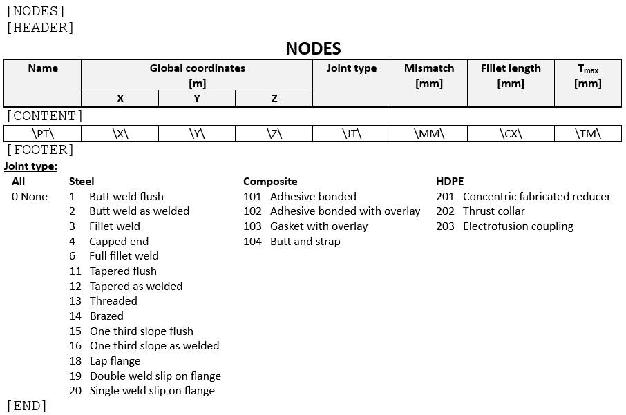
Between the [HEADER] section and the [CONTENT] section, user can define an introduction of the table, a title and table headers and units.
Between the [CONTENT] section and the [FOOTER] section, user can define a one line table (aligned with the header). On each cell, user can define properties. The software will repeat this row with every item of this type and fill the properties.
Between the [FOOTER] section and the [END] section, user can define a conclusion of the table or some remarks.
4.1 Properties
Depending of the type of the keyword, properties are recoverable.
A property is defined between 2 backslashes \XX\
4.1.1 Pipe section
| Property | Description | Unit Metric | Unit USA |
|---|---|---|---|
| \CD\ | Name | - | - |
| \AL\ | Description | - | - |
| \OD\ | Diameter | mm | in |
| \ID\ | Inside diameter | mm | in |
| \WT\ | Thickness | mm | in |
| \IN\ | Insulation thickness | mm | in |
| \SO\ | Operating density | - | - |
| \ST\ | Test density | - | - |
| \MA\ | Linear mass | kg/m | lb/ft |
| \CO\ | Corrosion | mm | in |
| \CI\ | Erosion | mm | in |
| \OV\ | Ovalization ratio | - | - |
| \LI\ | Liner thickness | mm | in |
| \TC\ | TopCoat thickness | mm | in |
| \EM\ | Special thickness | mm | in |
| \BT | Bend thickness | mm | in |
4.1.2 Beam section
| Property | Description | Unit Metric | Unit USA |
|---|---|---|---|
| \CD\ | Name | - | - |
| \AL\ | Description | - | - |
| \H\ | Height | mm | in |
| \B\ | Basis | mm | in |
| \TW\ | Web thickness | mm | in |
| \TF\ | Flange thickness | mm | in |
| \IX\ | Bending inertia X | cm^4 | in^4 |
| \IY\ | Bending inertia Y | cm^4 | in^4 |
| \IT\ | Torsional inertia | cm^4 | in^4 |
| \A\ | Area | cm² | in² |
| \AX\ | Reduced area X | cm² | in² |
| \AY\ | Reduced area Y | cm² | in² |
4.1.3 Regular material
| Property | Description | Unit Metric | Unit USA |
|---|---|---|---|
| \CD\ | Name | - | - |
| \AL\ | Description | - | - |
| \SG\ | Poisson’s ratio | - | - |
| \TX\ | Temperature max | °C | °F |
| \TA\ | Temperature ref | °C | °F |
| \RO\ | Density | kg/m³ | lb/ft³ |
| \TE\ | Temperature i | °C | °F |
| \EX\ | Thermal Expansion | 10^-6.mm/mm/°C | 10^-6.in/in/°F |
| \EH\ | Modulus of Elasticity | kN/mm² | 10^6.psi |
| \SH\ | Non-Class 1 Allowable Stress | N/mm² | ksi |
| \SY\ | Yield Stress | N/mm² | ksi |
| \SU\ | Ultimate Tensile Stress | N/mm² | ksi |
| \SM\ | Class 1 Allowable Stress | N/mm² | ksi |
| \CR\ | Creep | N/mm² | ksi |
| \GH\ | Shear Modulus | kN/mm² | 10^6.psi |
| \CO\ | Class 1 Thermal Conductivity | kJ/hr/m/°C | btu/hr/ft/°F |
| \DI\ | Class 1 Thermal Diffusivity | mm²/s | ft²/hr |
| \E2\ | Modulus of Elasticity 2 | kN/mm² | 10^6.psi |
4.1.4 Node
| Property | Description | Unit Metric | Unit USA |
|---|---|---|---|
| \PT\ | Name | - | - |
| \X\ | X global coordinate | m | ft |
| \Y\ | Y global coordinate | m | ft |
| \Z\ | Z global coordinate | m | ft |
| \JT\ | Joint type (see below) | - | - |
| \MM\ | Mismatch for welded joints | mm | in |
| \CX\ | Length of fillet weld Cx | mm | in |
| \TM\ | for Class 1 transition within 1:3 slope envelope | mm | in |
Joint type values :
    None = 0
    // For steel
    ButtWeldFlush = 1
    ButtWeldAsWelded = 2
    FilletWeld = 3
    CappedEnd = 4
    FullFilletWeld = 6
    TaperedFlush = 11
    TaperedAsWelded = 12
    Threaded = 13
    Brazed = 14
    OneThirdSlopeFlush = 15
    OneThirdSlopeAsWelded = 16
    LapFlange = 18
    DoubleWeldSlipOnFlange = 19
    SingleWeldSlipOnFlange = 20
    // For composite
    AdhesiveBonded = 101
    AdhesiveBondedWithOverlay = 102
    GasketWithOverlay = 103
    ButtAndStrap = 104
    // For HDPE
    ConcentricFabricatedReducer = 201
    ThrustCollar = 202
    ElectrofusionCoupling = 203
4.1.5 Element
| Property | Description | Unit Metric | Unit USA |
|---|---|---|---|
| \TY\ | Type | - | - |
| \PT1\ | Node1 name | - | - |
| \PT2\ | Node2 name | - | - |
| \LE\ | Length | m | ft |
| \RA\ | Bend radius (only for bend) | m | ft |
| \MA\ | Material description | - | - |
| \AL\ | Label | - | - |
| \XX\ | X-axis direction on X | - | - |
| \XY\ | X-axis direction on Y | - | - |
| \XZ\ | X-axis direction on Z | - | - |
| \CS\ | Section description | - | - |
| \CL\ | Piping code (empty for beam) | - | - |
Special properties for beam :
| Property | Description | Unit Metric | Unit USA |
|---|---|---|---|
| \J1\ | Joint type on Node 1 (see below) | - | - |
| \J2\ | Joint type on Node 2 (see below) | - | - |
| \BX\ | Buckling on X | - | - |
| \BY\ | Buckling on Y | - | - |
| \BZ\ | Buckling on Z | - | - |
| \LTB\ | Lateral Torsional Buckling (see below) | - | - |
Joint type values :
    None = 0
    Joint = 1
    BoltedJoint = 2
    WeldedJoint = 3
Lateral Torsional Buckling values :
    None = 0
    BothHingedUniform = 1
    BothHingedNodal = 2
    BothFixedUniform = 3
    BothFixedNodal = 4
    Moments = 5
    CantileverUniform = 6
    CantileverNodal = 7
4.1.6 DLCS
| Property | Description | Unit Metric | Unit USA |
|---|---|---|---|
| \PT\ | Node name | - | - |
| \XX\ | X-axis direction on X | - | - |
| \XY\ | X-axis direction on Y | - | - |
| \XZ\ | X-axis direction on Z | - | - |
| \ZX\ | Z-axis direction on X | - | - |
| \ZY\ | Z-axis direction on Y | - | - |
| \ZZ\ | Z-axis direction on Z | - | - |
4.1.7 Lumped mass
| Property | Description | Unit Metric | Unit USA |
|---|---|---|---|
| \PT\ | Node name | - | - |
| \X\ | X global coordinate | m | ft |
| \Y\ | Y global coordinate | m | ft |
| \Z\ | Z global coordinate | m | ft |
| \MA\ | Mass | ton | kips |
4.1.8 Restraint
| Property | Description | Unit Metric | Unit USA |
|---|---|---|---|
| \PT\ | Node name | - | - |
| \AL\ | Restraint type | - | - |
| \LO\ | Coordinate system (see below) | - | - |
| \LV\ | Level | - | - |
| \DESCR\ | Label | - | - |
| \SX\ | Translation stiffness on X | kN/mm | Kips/in |
| \SY\ | Translation stiffness on Y | kN/mm | Kips/in |
| \SZ\ | Translation stiffness on Z | kN/mm | Kips/in |
| \SPX\ | Rotation stiffness on X | kN.m/rad | Kips.ft/rad |
| \SPY\ | Rotation stiffness on Y | kN.m/rad | Kips.ft/rad |
| \SPZ\ | Translation stiffness on Z | kN.m/rad | Kips.ft/rad |
| \FO\ | Pre-compression/pre-tension force | kN | Kips |
Coordinate system values :
    G = Global
    L = Local to attached element
    N = Local to node's DLCS
4.1.9 Static case : Forces & moments on node
| Property | Description | Unit Metric | Unit USA |
|---|---|---|---|
| \PT\ | Node name | - | - |
| \CA\ | Load number | - | - |
| \TI\ | Load title | - | - |
| \FX\ | Force on X | kN | kips |
| \FY\ | Force on Y | kN | kips |
| \FZ\ | Force on Z | kN | kips |
| \MX\ | Moment on X | kN.m | kips.ft |
| \MY\ | Moment on Y | kN.m | kips.ft |
| \MZ\ | Moment on Z | kN.m | kips.ft |
| \LO\ | Local | - | - |
4.1.10 Static case : Restraints movement
| Property | Description | Unit Metric | Unit USA |
|---|---|---|---|
| \PT\ | Node name | - | - |
| \CA\ | Load number | - | - |
| \TI\ | Load title | - | - |
| \DX\ | Displacement on X | mm | in |
| \DY\ | Displacement on Y | mm | in |
| \DZ\ | Displacement on Z | mm | in |
| \RX\ | Rotation on X | rad | rad |
| \RY\ | Rotation on Y | rad | rad |
| \RZ\ | Rotation on Z | rad | rad |
4.1.11 Static case : Distributed loads
| Property | Description | Unit Metric | Unit USA |
|---|---|---|---|
| \TY\ | Type | - | - |
| \PT1\ | Node1 name | - | - |
| \PT2\ | Node2 name | - | - |
| \CA\ | Load number | - | - |
| \TI\ | Load title | - | - |
| \X\ | Load on X | N/m | lb/ft |
| \Y\ | Load on Y | N/m | lb/ft |
| \Z\ | Load on Z | N/m | lb/ft |
4.1.12 Static case : Wind loads
| Property | Description | Unit Metric | Unit USA |
|---|---|---|---|
| \TY\ | Type | - | - |
| \PT1\ | Node1 name | - | - |
| \PT2\ | Node2 name | - | - |
| \CA\ | Load number | - | - |
| \TI\ | Load title | - | - |
| \PR\ | Pressure | N/m² | lb/ft² |
| \X\ | Wind direction on X | - | - |
| \Y\ | Wind direction on Y | - | - |
| \Z\ | Wind direction on Z | - | - |
4.1.13 Static case : Snow loads
| Property | Description | Unit Metric | Unit USA |
|---|---|---|---|
| \TY\ | Type | - | - |
| \PT1\ | Node1 name | - | - |
| \PT2\ | Node2 name | - | - |
| \CA\ | Load number | - | - |
| \TI\ | Load title | - | - |
| \PR\ | Pressure | N/m² | lb/ft² |
4.1.14 Static case : Operating conditions
| Property | Description | Unit Metric | Unit USA |
|---|---|---|---|
| \TY\ | Type | - | - |
| \PT1\ | Node1 name | - | - |
| \PT2\ | Node2 name | - | - |
| \CA\ | Load number | - | - |
| \TI\ | Load title | - | - |
| \TE\ | Temperature | °C | °F |
| \PR\ | Pressure | N/m² | lb/ft² |
4.1.15 Static case : Densities
| Property | Description | Unit Metric | Unit USA |
|---|---|---|---|
| \TY\ | Type | - | - |
| \PT1\ | Node1 name | - | - |
| \PT2\ | Node2 name | - | - |
| \CA\ | Load number | - | - |
| \TI\ | Load title | - | - |
| \RO\ | Density | - | - |
4.1.16 Static case : Stratifications
| Property | Description | Unit Metric | Unit USA |
|---|---|---|---|
| \TY\ | Type | - | - |
| \PT1\ | Node1 name | - | - |
| \PT2\ | Node2 name | - | - |
| \CA\ | Load number | - | - |
| \ME\ | Stratification method (see below) | - | - |
| \AL\ | Mean coef. of thermal expansion of pipe | 10^-6mm/mm/°C | 10^-6in/in/°F |
| \T1\ | Temperature at bottom of the pipe or temp. gradient Gu | °C or °C/mm | °F or °F/in |
| \T2\ | Temperature at top of the pipe or temp. gradient Gv | °C or °C/mm | °F or °F/in |
| \V1\ | Vertical coordinate of the discontinuity or laminar flow down | mm | in |
| \V2\ | Vertical coordinate of the laminar flow up | mm | in |
| \X\ | X component of the local V vector | - | - |
| \Y\ | Y component of the local V vector | - | - |
| \Z\ | Z component of the local V vector | - | - |
Stratification method values :
    HorizontalLinear = 0
    HorizontalStep = 1
    HorizontalLaminar = 2
    HorizontalGu = 3
    Skewed = 4
    General = 5
4.1.17 Static case : Cold springs
| Property | Description | Unit Metric | Unit USA |
|---|---|---|---|
| \TY\ | Type | - | - |
| \PT1\ | Node1 name | - | - |
| \PT2\ | Node2 name | - | - |
| \CA\ | Load number | - | - |
| \LE\ | Length change | mm | in |
4.1.18 Static case : Accelerations
| Property | Description | Unit Metric | Unit USA |
|---|---|---|---|
| \TY\ | Type | - | - |
| \PT1\ | Node1 name | - | - |
| \PT2\ | Node2 name | - | - |
| \CA\ | Load number | - | - |
| \TI\ | Load title | - | - |
| \GX\ | Fraction of G on X | - | - |
| \GY\ | Fraction of G on Y | - | - |
| \GZ\ | Fraction of G on Z | - | - |
4.1.19 Static case
| Property | Description | Unit Metric | Unit USA |
|---|---|---|---|
| \CA\ | Load number | - | - |
| \TI\ | Load title | - | - |
| \TY\ | Load category (see below) | - | - |
| \LV\ | Level | - | - |
| \EQ\ | Equation (see below) | - | - |
| \CF\ | Check fasteners (structure only) | - | - |
Category values :
    OperatingWeight = 0
    TestWeight = 1
    EmptyWeight = 2
    DesignWeight = 3
    Wind = 4
    Snow = 5
    Distributed = 6
    Acceleration = 7
    SAM = 8
    Thermal = 9
    Settlement = 10
    ColdSpring = 11
    Dummy = 12
    UserDefined = 13
Equation values :
    None (no stress calculation) = 1
    Equation 6 (sustained) = 2
    Equation 10 B (occasional) = 3
    Equation 10 C (occasional) = 4
    Equation 10 D (occasional) = 5
    Equation 10 T (test) = 6
    Equation 7 (thermal expansion) = 7
    Equation 8 (thermal expansion + sustained) = 8
    Equation 9 (settlement) = s
4.1.20 Time history event : Dynamic forces & moments on node
| Property | Description | Unit Metric | Unit USA |
|---|---|---|---|
| \PT\ | Node name | - | - |
| \TI\ | Event title | - | - |
| \FX\ | Force on X | kN | kips |
| \FY\ | Force on Y | kN | kips |
| \FZ\ | Force on Z | kN | kips |
| \MX\ | Moment on X | kN.m | kips.ft |
| \MY\ | Moment on Y | kN.m | kips.ft |
| \MZ\ | Moment on Z | kN.m | kips.ft |
4.1.21 Time history cases
| Property | Description | Unit Metric | Unit USA |
|---|---|---|---|
| \CA\ | Load number | - | - |
| \TI\ | Load title | - | - |
| \LV\ | Level | - | - |
| \EQ\ | Equation (see above) | - | - |
| \EV\ | Event number | - | - |
| \DA\ | Damping value | - | - |
| \RC\ | Rigid correction | - | - |
| \RM\ | Resultant moment | - | - |
| \ES\ | Explicit scheme | - | - |
| \TS\ | Time step | - | - |
| \AR\ | Archive rate | - | - |
| \CF\ | Check fasteners (structure only) | - | - |
4.1.22 Class 1 thermal case : Transients
| Property | Description | Unit Metric | Unit USA |
|---|---|---|---|
| \TY\ | Type | - | - |
| \PT1\ | Node1 name | - | - |
| \PT2\ | Node2 name | - | - |
| \CA\ | Load number | - | - |
| \TI\ | Load title | - | - |
| \TR\ | Transient name | - | - |
4.1.23 Class 1 case : Load sets
| Property | Description | Unit Metric | Unit USA |
|---|---|---|---|
| \TI\ | Load title | - | - |
| \RF\ | Reference case number | - | - |
| \SI\ | Situation number | - | - |
| \TR\ | Thermal case number | - | - |
| \CY\ | Number of cycles | - | - |
| \PR\ | Pressure case number | - | - |
| \MO\ | Moment case number | - | - |
| \DY\ | Dynamic load flag | - | - |
4.1.24 Spectrum
| Property | Description | Unit Metric | Unit USA |
|---|---|---|---|
| \EV\ | Event number | - | - |
| \TI\ | Load title | - | - |
| \NA\ | Spectrum name | - | - |
| \XA\ | Period or frequency | - | - |
| \ME\ | Interpolation method (see below) | - | - |
| \SH\ | Shift value | % | % |
| \DA\ | Damping value | - | - |
| \DU\ | Duration value | s | s |
Interpolation method values :
    Linear / Linear acceleration = 0
    Linear frequency / Linear acceleration = 1
    Linear period / Linear acceleration = 2
    Log frequency / Linear acceleration = 3
    Log frequency / Log acceleration = 4
4.1.25 Primary floor response cases
| Property | Description | Unit Metric | Unit USA |
|---|---|---|---|
| \CA\ | Load number | - | - |
| \TI\ | Load title | - | - |
| \LV\ | Level | - | - |
| \EV\ | Event number | - | - |
| \EQ\ | Equation (see above) | - | - |
| \IM\ | Inter modal combination (see below) | - | - |
| \IL\ | Inter level combination (see below) | - | - |
| \OR\ | Order (see below) | - | - |
| \RC\ | Rigid correction (see below) | - | - |
| \X\ | X factor | - | - |
| \Y\ | Y factor | - | - |
| \Z\ | Z factor | - | - |
| \CF\ | Check fasteners (structure only) | - | - |
Inter modal combination values :
    Grouping = 1
    Ten percent = 2
    Double sum = 3
    SRSS = 4
    All coupling = 5
    Rosenblueth = 6
    Der Kiureghian = 7
Inter level combination values :
    Absolute without phase = 0
    SRSS without phase = 1
    Algebraic = 2
    Absolute with phase = 3
    SRSS with phase = 4
    Envelope = 5
    SRSS with counterphase = 6
Order values :
    Interlevel / Intermodal / Interspatial = 0
    Interlevel / Interspatial / Intermodal = 1
    Intermodal / Interlevel / Interspatial = 2
Rigid correction values :
    SRSS = 0
    None = 1
    Absolute = 2
    SRSS with modal = 3
    Gupta = 4
    Lindley-Yow = 5
4.1.26 Secondary floor response cases
| Property | Description | Unit Metric | Unit USA |
|---|---|---|---|
| \CA\ | Load number | - | - |
| \TI\ | Load title | - | - |
| \LV\ | Level | - | - |
| \EV\ | Event number | - | - |
| \EQ\ | Equation (see above) | - | - |
| \ME\ | Method of combination (see below) | - | - |
| \TP\ | Treat as primary | - | - |
| \X\ | X factor | - | - |
| \Y\ | Y factor | - | - |
| \Z\ | Z factor | - | - |
| \CF\ | Check fasteners (structure only) | - | - |
Combination method values :
    Absolute = 0
    SRSS = 1
4.1.27 Combination cases
| Property | Description | Unit Metric | Unit USA |
|---|---|---|---|
| \CA\ | Load number | - | - |
| \TI\ | Load title | - | - |
| \RF\ | Reference case number | - | - |
| \LV\ | Level | - | - |
| \EQ\ | Equation (see above) | - | - |
| \ME\ | Method of combination (see below) | - | - |
| \DY\ | Dynamic load flag | - | - |
| \CY\ | Number of cycles | - | - |
| \TY\ | Analysis type | - | - |
| \C1\ | factor(i) x case(i) | - | - |
| \CF\ | Check fasteners (structure only) | - | - |
Combination method values :
    Algebraic = 0
    Absolute = 1
    SRSS = 2
    Seismic = 3
    MaxAbsolute = 4
    MaxResultant = 5
    MaxAlgebraic = 6
    MinAlgebraic = 7
    Range = 8
    MomentRange = 9
    StressRange = 10
4.1.28 Combination stress cases
| Property | Description | Unit Metric | Unit USA |
|---|---|---|---|
| \CA\ | Load number | - | - |
| \TI\ | Load title | - | - |
| \RF\ | Reference case number | - | - |
| \LV\ | Level | - | - |
| \EQ\ | Equation (see above) | - | - |
| \ME\ | Method of combination (see above) | - | - |
| \MU\ | Allowable multiplier | - | - |
| \MA\ | factor x sustained load case | - | - |
| \MB\ | factor x occasional load case | - | - |
| \MC\ | factor x thermal load case | - | - |
4.1.29 External cases
| Property | Description |
|---|---|
| \CA\ | Load number |
| \TI\ | Load title |
| \SN\ | External study name |
| \LC\ | External study load case number |
4.1.30 Results : Displacements
| Property | Description | Unit Metric | Unit USA |
|---|---|---|---|
| \PT\ | Node name | - | - |
| \CA\ | Load number | - | - |
| \TI\ | Load title | - | - |
| \DX\ | X global displacement | mm | in |
| \DY\ | Y global displacement | mm | in |
| \DZ\ | Z global displacement | mm | in |
| \RX\ | X global rotation | Rad | Rad |
| \RY\ | Y global rotation | Rad | Rad |
| \RZ\ | Z global rotation | Rad | Rad |
4.1.31 Results : Forces & moments on element’s nodes
| Property | Description | Unit Metric | Unit USA |
|---|---|---|---|
| \TY\ | Type | - | - |
| \PT\ | Node extremity name | - | - |
| \CA\ | Load number | - | - |
| \TI\ | Load title | - | - |
| \FX\ | Force on X | N | lb |
| \FY\ | Force on Y | N | lb |
| \FZ\ | Force on Z | N | lb |
| \MX\ | Moment on X | N.m | lb.ft |
| \MY\ | Moment on Y | N.m | lb.ft |
| \MZ\ | Moment on Z | N.m | lb.ft |
4.1.32 Results : Reactions on restraint’s node
| Property | Description | Unit Metric | Unit USA |
|---|---|---|---|
| \PT\ | Node name | - | - |
| \CA\ | Load number | - | - |
| \TI\ | Load title | - | - |
| \FX\ | Force on X | N | lb |
| \FY\ | Force on Y | N | lb |
| \FZ\ | Force on Z | N | lb |
| \MX\ | Moment on X | N.m | lb.ft |
| \MY\ | Moment on Y | N.m | lb.ft |
| \MZ\ | Moment on Z | N.m | lb.ft |
4.1.33 Results : Stresses on elements
| Property | Description | Unit Metric | Unit USA |
|---|---|---|---|
| \TY\ | Type | - | - |
| \PT1\ | Node 1 name | - | - |
| \PT2\ | Node 2 name | - | - |
| \CA\ | Load number | - | - |
| \TI\ | Load title | - | - |
| \ST\ | Stress max | N/mm² | ksi |
4.1.34 Results : Anchor plate max ratios
| Property | Description | Unit Metric | Unit USA |
|---|---|---|---|
| \PT\ | Node name | - | - |
| \CA\ | Load number | - | - |
| \TI\ | Load title | - | - |
| \RA\ | Ratio max | - | - |
4.1.35 Results : Beam joint ratios
| Property | Description | Unit Metric | Unit USA |
|---|---|---|---|
| \TY\ | Type | - | - |
| \PT\ | Node name | - | - |
| \CA\ | Load number | - | - |
| \TI\ | Load title | - | - |
| \RA\ | Ratio max | - | - |
4.1.36 Results : Finite element analysis fastener report
| Property | Description | Unit Metric | Unit USA |
|---|---|---|---|
| \LINE\ | Report line(i) | - | - |
4.1.37 Results : Finite element analysis node
| Property | Description | Unit Metric | Unit USA |
|---|---|---|---|
| \ID\ | Node id | - | - |
| \X\ | X coordinate | mm | in |
| \Y\ | Y coordinate | mm | in |
| \Z\ | Z coordinate | mm | in |
| \UX\ | X displacement | mm | in |
| \UY\ | Y displacement | mm | in |
| \UZ\ | Z displacement | mm | in |
| \STRESS\ | Stress | N/mm² | ksi |
| \STRAIN\ | Strain | % | % |
| \CO\ | Compression | N/mm² | ksi |