Create bends
When you click on the Add bend button without selection, the left panel shows a message :
Select a node or 2 nodes to join
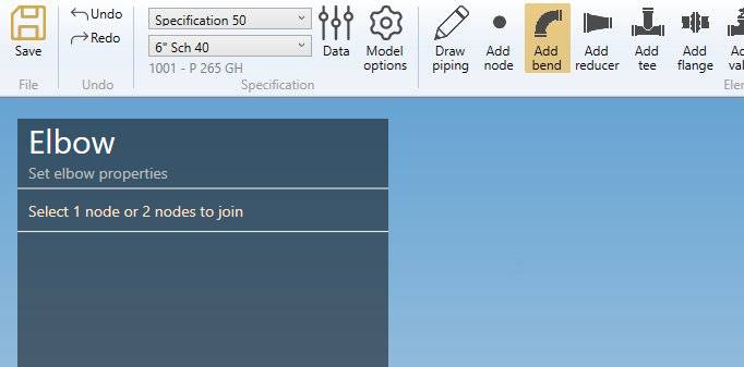
The selection mode is automatically set to POINT. You can so directly select a node.
1. Create first bend
Select an isolated node and click on the Add bend button :
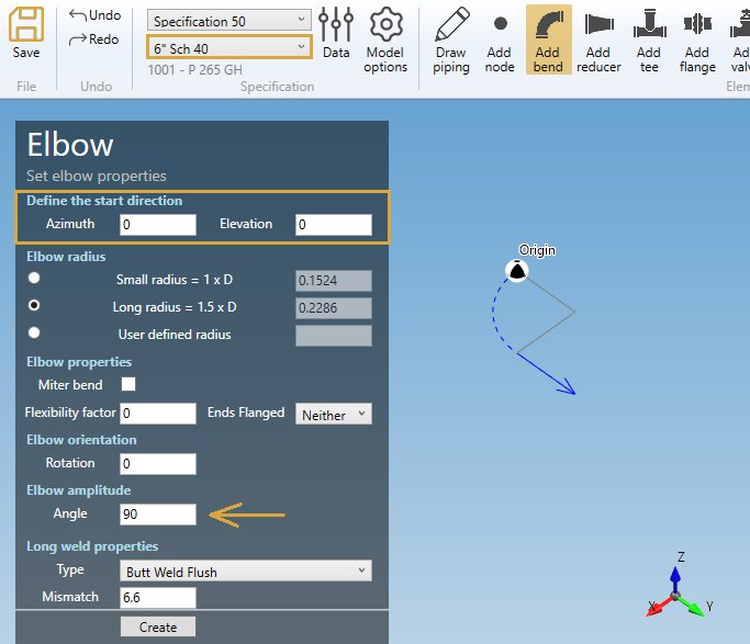
MetaPiping asks you to define the start direction with 2 angles :
- Azimuth = Horizontal angle in °
- Elevation = Vertical angle in °
The default direction is the global X axis.
But with the default Amplitude of 90°, the elbow will have the global Y axis as final direction.
The properties are explained in §2.
Click on the Create button to add a bend.
You can Undo this command.
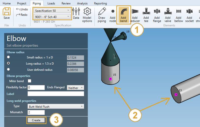
2. Create a bend from another element
- Select the current section/material in the specification box.
- Select a node.
- Click the Add bend button
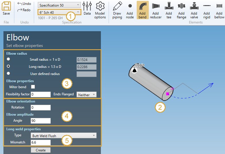
2.1 Elbow properties (3)
In this example, the values correspond to current specification preset.
RADIUS :
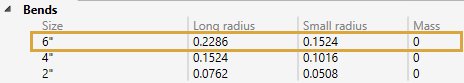
MetaPiping sets the Long radius by default but you can change it (Small radius or user defined radius)
| Property | Unit Metric | Unit USA |
|---|---|---|
| Radius | m | ft |
To know the UNIT of the value, just let the mouse over the cell.
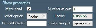
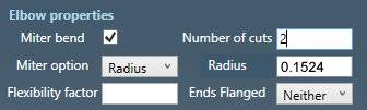
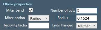
MITER :
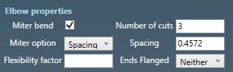
You can define a miter bend by checking the checkbox and define the number of cuts and if it is based on the radius or on a spacing.
| Property | Unit Metric | Unit USA |
|---|---|---|
| Spacing | m | ft |
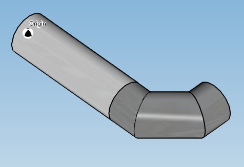
Here are some examples.
Radius & cuts = 1 :
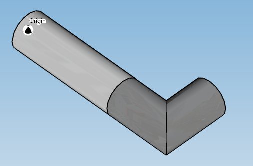
Radius & cuts = 2 :
Radius & cuts = 3 :
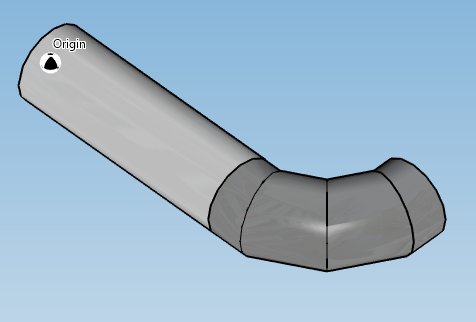
Spacing & cuts = 3, MetaPiping calculates the default spacing for an identical result :
Spacing = 0.6 :
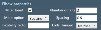
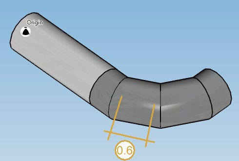
ATTENTION, in this case, the node extremity of the previous pipe is moved to respect the bend construction
FLEXIBILITY FACTOR :
User can define the flexibility factor of the bend.
This flexibility factor will be used for all load cases.
Default = 0 or blank = default special k Factor in the code.
ENDS FLANGED :
You can choose between :
- Neither end flanged
- One end flanged
- Both ends flanged
2.2 Elbow orientation (4)
Here are some examples of Rotation and Amplitude values :
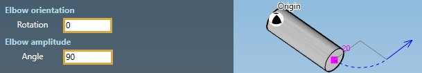
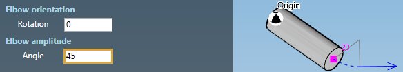
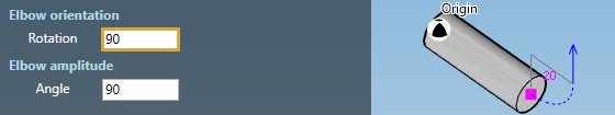
Rotation and Angle are in °.
2.3 Long weld properties (5)
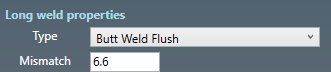
For the type, you can choose between :
- None
- Butt weld flush
- Butt weld as welded
Based on this property, define the Long weld mismatch [mm or in].
In this example, the default values correspond to current specification preset :

2.4 Label
You can define a label to this element. The labels are shown with the node names view button.

2.5 Next node
You can set the next extremity node name of the element. If blank, the software will define it automatically. The software will also check that the name doesn’t already exist.
3. Create a bend with 2 points
- Click the Add bend button
- Select two nodes of coplanar elements
- Click the Create button after defining the section and the bend properties
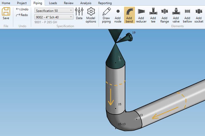
This will extend the 2 adjacent elements and place a bend with the desired radius.
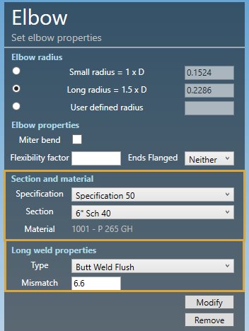
4. Modify/Remove a bend
Change the Selection mode to ELEMENT and select a bend :
Click here for more information about the selection tool.
You can modify the radius of the bend. The lengths of the adjacent pipes will be adapted.
You can also modify all bend properties.
SECTION AND MATERIAL :
You can change the specification and section/material of the bend.
LONG WELD :
You can change the Long weld properties :
For the type, you can choose between :
- None
- Butt weld flush
- Butt weld as welded
Based on this property, define the Long weld mismatch [mm or in].
In this example, the default values correspond to current specification preset :
Click on the Modify button to change the selected bend with these new properties.
You can undo this command.
Click on the Remove button to delete the selected bend.
You can undo this command.