Combination cases
This case consists of combining the results of load cases, dynamic cases or previously calculated
combination cases to form a new case.
When selecting Combination cases, all existing combinations are listed in the combobox :

The cases appear with their Case number + Title.
1. General
When editing, the definition window shows up :
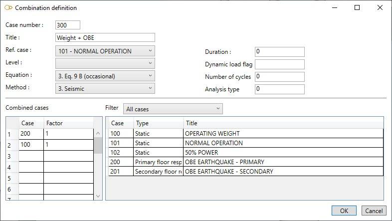
Enter a Case number and a Title.
Ref. case :
Operating pressures (and allowable stresses) of the reference case will be used for this case. The calculation of the allowable stresses depends on the current calculation code.
Click here for more information about all possible codes.
Level :
This field is intended for nuclear piping codes only. The possible values are : A (normal conditions), B (upset), C (emergency), D (faulted) and T (test).
Equation :
The equations are code-dependent.
Method :
- 0- Algebraic addition
- 1- Absolute addition
- 2- SRSS
- 3- Seismic
- 4- Maximum absolute
- 6- Algebraic maximum
- 7- Algebraic minimum
- 8- Range
- 9- Max resultant moment range
- S- Max thermal stress range
Duration :
This field (expressed in hours) is used for HDPE and RCC-MRx codes only.
- For HDPE : duration determines the allowable stress of HDPE materials
- For RCC-MRx : duration allows to calculate the creep effects. If not entered or 0, the duration entered in the reference case is used
Dynamic load flag :
This field is used for Class 1 codes only.
- For ASME Class 1 : the flag is a number from 1 to 9 that identifies the dynamic moments to be used in Equation 13
- For RCC-M Class 1 : the flag with number 1 identifies the operational earthquake
- For RCC-MRx : the flag is a number from 1 to 3 that identifies the dynamic moments to be used for Type S damages
Number of cycles :
This field is used for Class 1 codes only.
- For ASME Class 1 and RCC-MRx : number of sub-cycles predicted for each occurrence of the dynamic event (default = 1)
- For RCC-M Class 1 : number of occurrences of the seismic event if the analysis type is 0, or number of seismic sub-cycles if the analysis type is 1
Analysis type :
This field is used for RCC-M Class 1 and RCC-MRx codes only.
- For RCC-M Class 1 : enter 0 (or blank) for the total earthquake moments and 1 for the primary (inertial) earthquake moments
- For RCC-MRx : enter 1 for the primary dynamic moments and 6 for the secondary dynamic moments. 0 (or blank) may optionally be entered for the total dynamic moments. If no combination case with analysis type equal to 1 is entered, the primary dynamic moments are then taken equal to the total dynamic moments
2. Combined cases
Enter the number of the constituent cases and the corresponding factor (1) :
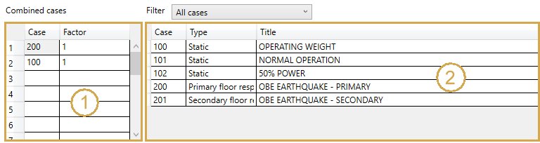
On right side, as a reminder, the list of all cases (2). You can filter them by selecting the type :
- All
- Static
- Dynamic
- Combination