Draw structure
1. New project
Select a current section.
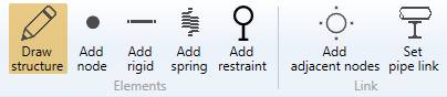
Click on the Draw structure button :
As we start the modeling, we need to create a First node :
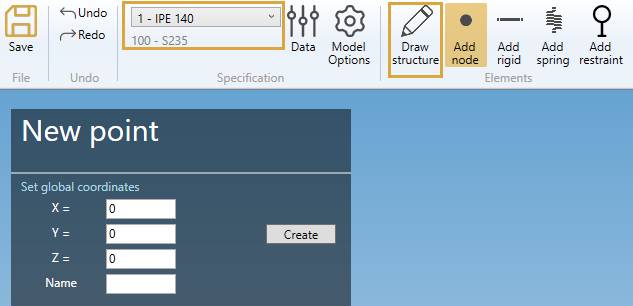
Click here for more information about the First node creation.
1.2. Draw the first beam
After the first node has been created, you can draw your first beam :
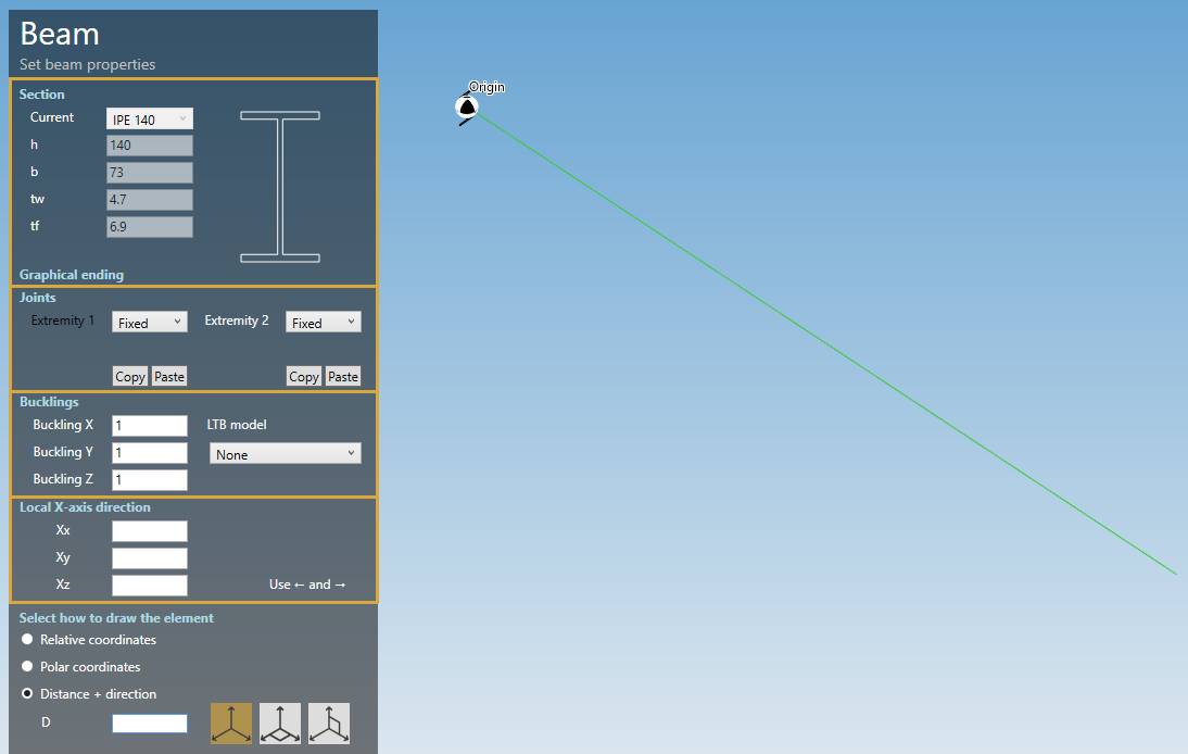
The current section is the selected one in the upper specification ribbon.
Some properties are shown :
| Property | Description | Unit Metric | Unit USA |
|---|---|---|---|
| h | Height | mm | in |
| b | Width | mm | in |
| tw | Web thickness | mm | in |
| tw | Flange thickness | mm | in |
To know the UNIT of the value, just let the mouse over the cell.
Is cable checkbox can be used to define element that works only in traction (like cable).

For better vizualisation purpose, a beam with Cable option activated will appear with its section color + hatching.
You can define the joints, the buckling factors and the local-X axis direction. See below.
The only thing you have to do is to select how to draw the pipe.
Click here for more information about the orientation tool.
2. Draw structure
When you click on the Draw structure button without selection, the left panel shows a message :
Select a node
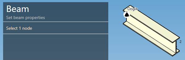
The selection mode is automatically set to POINT. You can so directly select a node.
2.1 Intermediate node
You can start a new beam on an intermediate point on the beam under mouse :
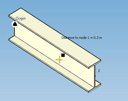
Once the distance from the first node of the beam is correct, CLICK on the left mouse button.
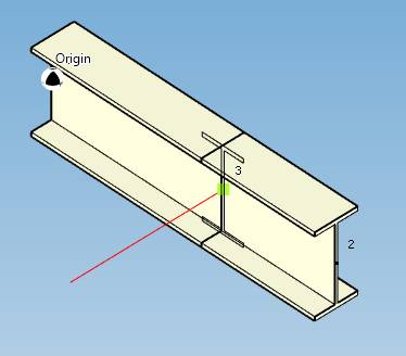
MetaStructure will automatically cut the beam and start a new beam from this new node :
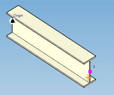
If you want to start from an extremity, be careful to have the extremity node in MAGENTA :
2.2 End of beam
You can draw a beam in different way :
- With the orientation tool :
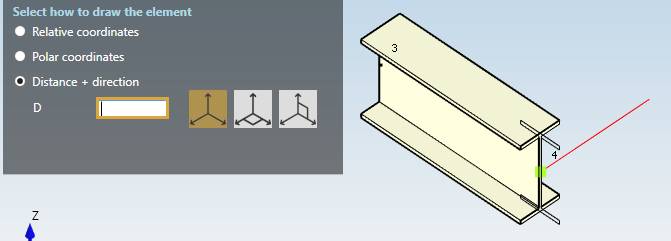
Choose a direction and write the Length with the numpad of the keyboard and press Enter to create the beam.
Click here for more information about the orientation tool.
- That ends at an existing node :
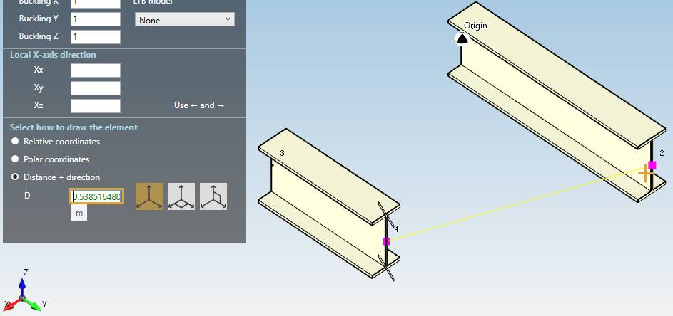
The node must be in MAGENTA color. The distance is automatically set in the cell. Just click the node or press Enter to create the beam.
- That ends at a projection X/Y/Z of a Reference node (in green) :
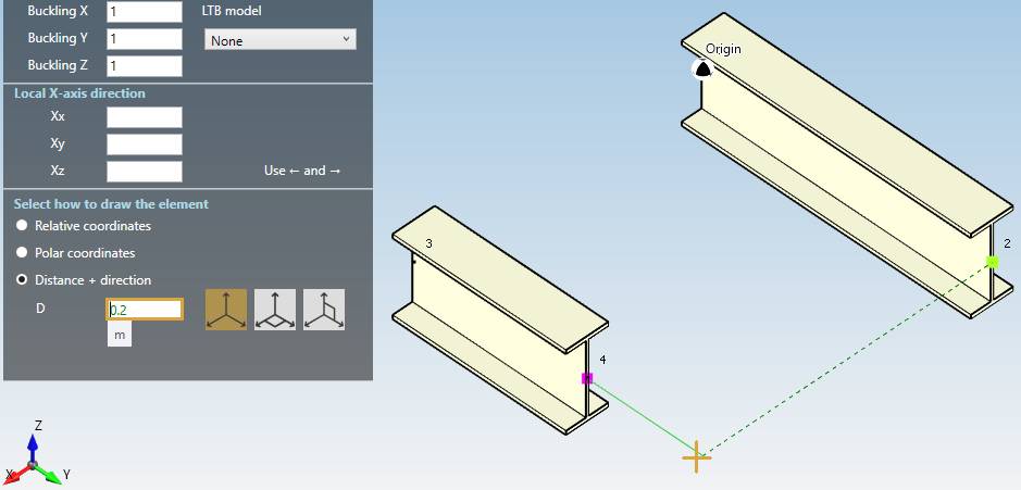
To define a Reference point, just move the mouse near an existing node -> it comes green.
The distance is automatically set in the cell. Just click the node or press Enter to create the beam.
- That ends at an intermediate node :
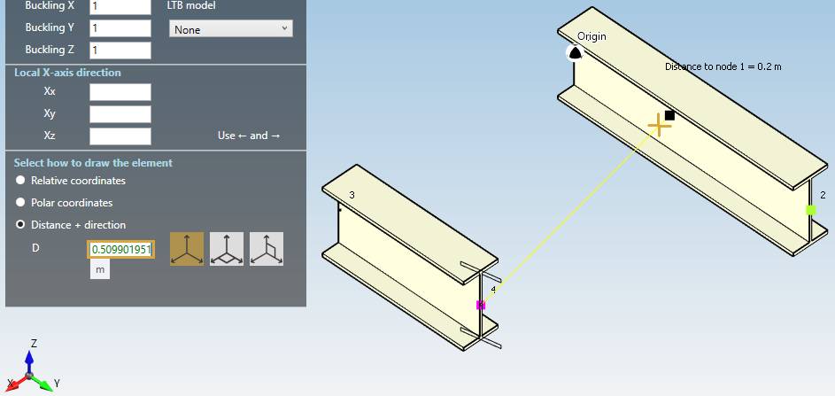
The distance is automatically set in the cell. Just click the node or press Enter to create the beam.
MetaStructure will automatically cut the beam
- That ends perpendicular to another beam :
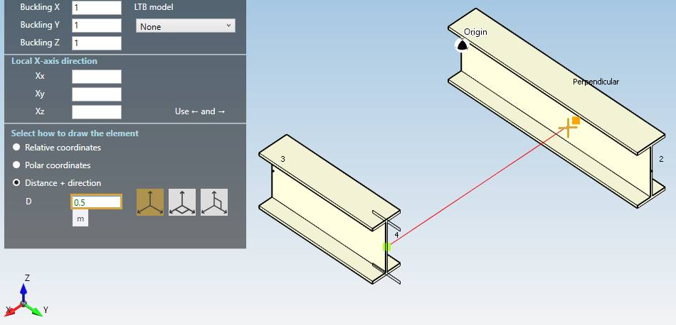
The distance is automatically set in the cell. Just click the node or press Enter to create the beam.
MetaStructure will automatically cut the beam.
3. Graphical ending
MetaStructure lets you define a graphical ending of every beams:
Click here for more information about the graphical endings.
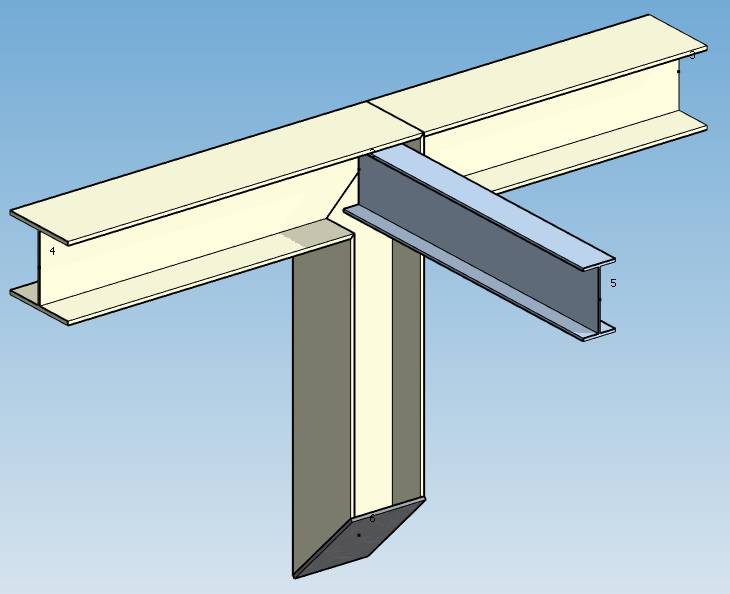
4. Joints
MetaStructure proposes several assemblies for each extremity of a beam :
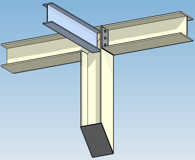
Example of a bolting plate
Click here for more information about assemblies.
5. Bucklings
The buckling values are factors that multiply the real length of the beam to get the buckling lengths :
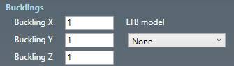
| Property | Description | Default |
|---|---|---|
| Buckling X | buckling factor in the weak inertia plane | 1 |
| Buckling Y | buckling factor in the strong inertia plane | 1 |
| Buckling Z | the lateral-torsional buckling factor | 1 |
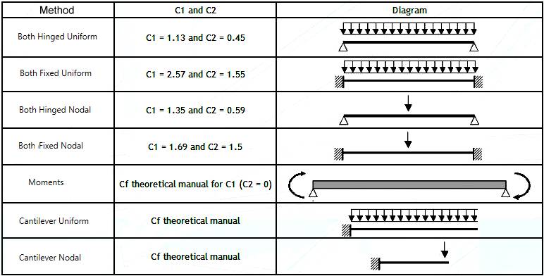
The Lateral-Torsional Buckling model (LTB) must be defined for the calculation of the elastic critical moment according to Eurocode 3.
This critical moment depends on the coefficients C1 and C2 :
6. Local X-axis direction
The default local-X direction for a beam is :
| X-axis | Global vertical axis | Default |
|---|---|---|
| Vertical beams | Z | (0, 1, 0) |
| Non vertical beams | Z | (0, 0, 1) |
| Vertical beams | Y | (0, 0, 1) |
| Non vertical beams | Y | (0, 1, 0) |
X-axis is always the weak axis, Y-axis the strong axis and Z-axis the axis of the beam from Node1 to Node2.
During modeling, you can set the values or press –> or <– to rotate the section by 90° :
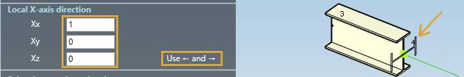
The section is directly drawn as a preview.
When selecting a beam, you can Show/Hide the local X-axis direction and modify it :
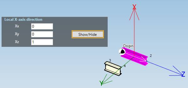
Changing the local X-axis direction will turn the section around its Z-axis.