Piping
After creating a new piping study and pressing the Edit button, a window appears to define the calculation code :
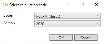
Set the Code and Edition and press OK : new tabs appear in the ribbon menu on top of the application :
- Piping
- Load - click here to have more information about loading
- Review - click here to have more information about review tools
- Analysis - click here to have more information about analysis
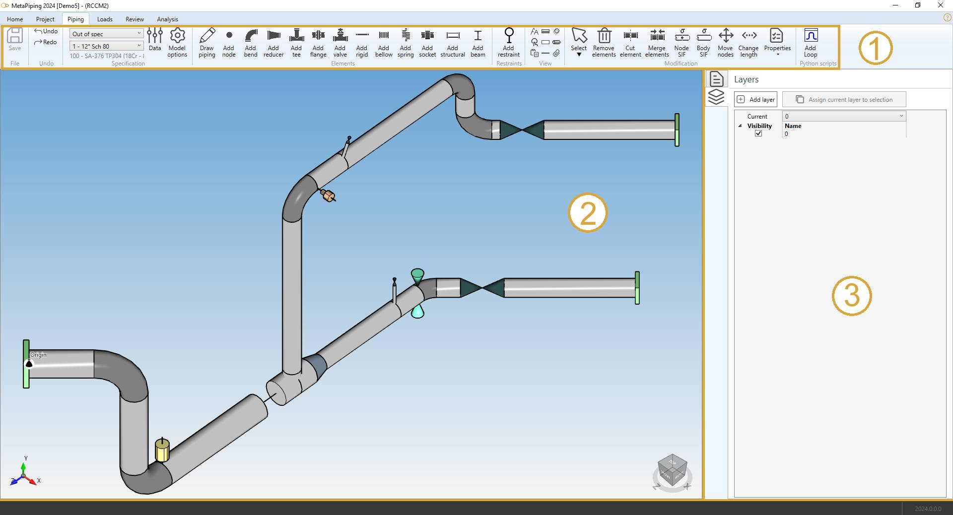
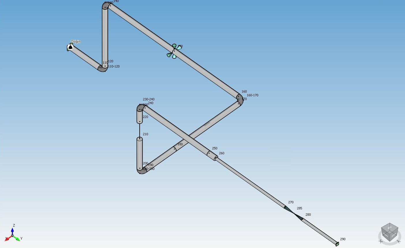
The Piping screen consists of a ribbon menu (1), a 3D visualization engine (2) and a data panel on the right (3).
The Data Panel can be opened/closed with the shortcut F2
1. Ribbon menu

1.1 File
During the design of the model, every command is automatically saved in a temporary file (conception.~metaL).
You can decide to save the last modifications or cancel it and return to the study screen.
A floppy disk on the left side of the ribbon indicates the state of the file on disk :
 means that everything has been saved.
 means that something has changed and the MetaL needs to be saved.
If the application crashes, MetaPiping will prompt to reopen the last modifications
1.2 Undo/Redo

Every command in MetaPiping is stored in a command list.
You can navigate through this list by pressing the Undo/Redo buttons.
1.3 Specification
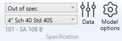
This group of controls lets you define the current Section/Material for the next elements.
You have an access to a window that defines the piping sections and materials for the current model.
You have an access to the model options (code, edition, calculation options…).
Click here to have more information about the Data button and the Model options button.
1.4 Elements
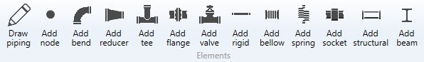
Click here to have more information about piping element creation.
1.5 Restraints
Click here to have more information about restraints.
1.6 View options
 show/hide the node name
 show/hide the node point
 shows/hides the labels
 shows/hides the origin symbol
 shows/hides the masses
 modify the font
 show the structure in shaded mode
 show the structure in hidden lines mode
 show the structure in wireframe mode
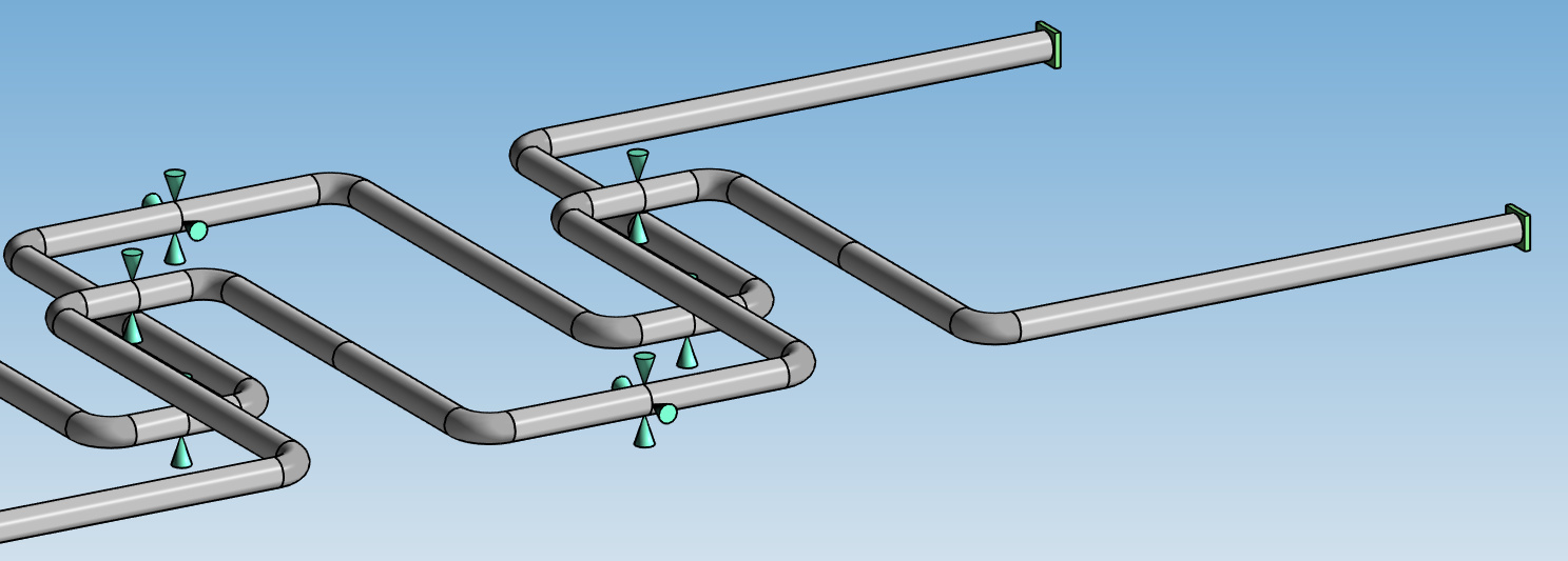
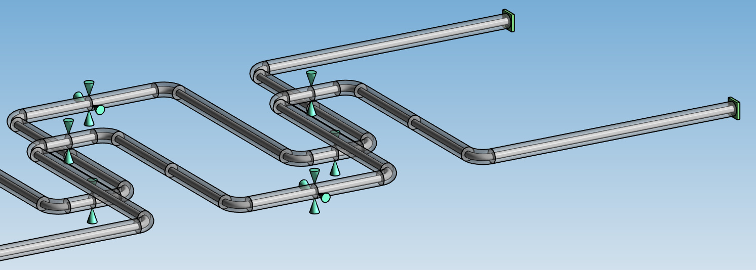
 shows/hides the restraints
 increase the restraint’s size
 decrease the restraint’s size
 shows/hides the linked and structure study models
copy the 3D view to the clipboard
 shows/hides the inner pipes
This last tool is useful to see the piping elements inside others :
Tip: if the Node name view is active, not all nodes will be shown during navigation to not slow down the application!
1.7 Modification tools
Click here to have more information about all modification tools.
1.8 Python scripts
MetaPiping lets you create your own tools.
If a tool is missing, user can create his own command that can interact with the user and modify the selected elements or the whole model.
MetaPiping will take care of the Undo/Redo mechanism.
Click here to have more information about python script creation.
See an example of a Design script : Replace a selected pipe by a loop
2. 3D Visualization
MetaPiping is equipped with a powerful 3D engine :
2.1 Navigation
You navigate inside the view with the middle button of the mouse pressed :

hold down the CTRL key during navigation to translate the view.
You zoom in by scrolling the mouse wheel up :

You zoom out by scrolling the mouse wheel down :

You zoom all by double click the mouse wheel button :
Tip: if the Node name view is active, not all nodes will be shown during navigation to not slow down the application!
2.2 Axis
The global axis are shown in the bottom left corner of the screen :

2.3 Predefined views
An interactive cube with predefined views is shown in the bottom right corner of the screen :

- Click on top corners of the cube to change to predefined axonometric view.
- Click twice on the faces of the cube to change to 2D views.
3. Data panel
The Data Panel can be opened/closed with the shortcut F2.
The data panel can be windowed or docked by clicking on the lower left button :

3.1 PIPESTRESS editor
The Plugin PIPESTRESS converts automatically every command of MetaPiping into HIGH FIDELITY FRE file format.
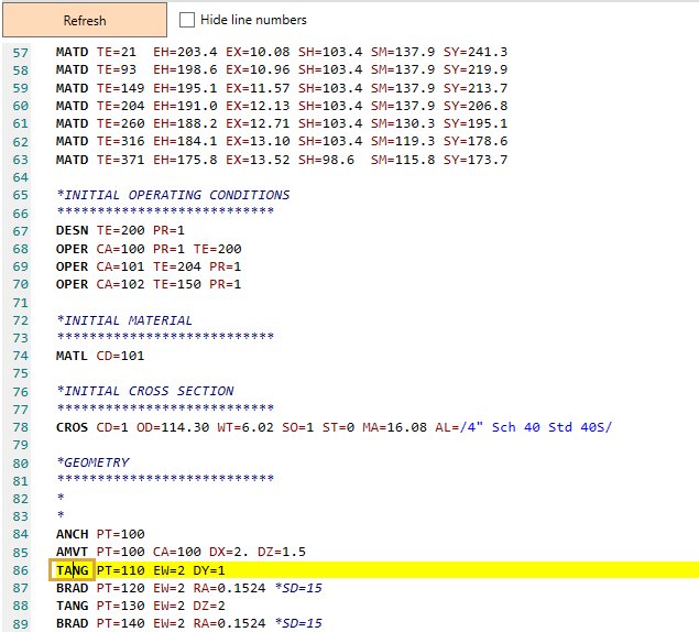
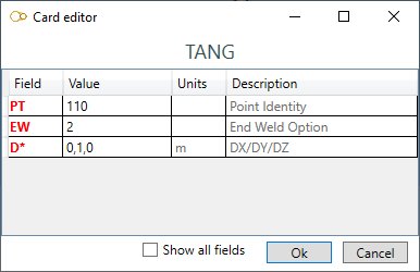
- Double click on a card to open a window with all fields :
-
You can write/change the file by yourself in this editor. Click on button
 on top (or F6) to update the model with the content of the editor.
 -
Click on button
 (or F9) to insert a new card at the current cursor position.
 -
Select a line and click on button
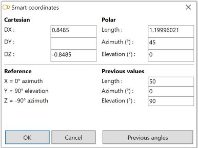
 (or F5) to open the Smart Coordinates window :
-
Select a line and click on button
 (or F9) to select the element or support in the 3D view.
 -
Click on button
 or
or  to increase or decrease the font size.
 -
Click on button
 to toggle the line numbers.
 -
Select a line and press F1 to open PIPESTRESS help (if path is defined in the settings).
-
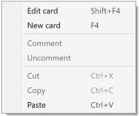
Right click to open the popup menu :
Click here to have more information about the settings.
Attention, this action is irreversible
3.2 Layers
MetaPiping let you simplify your visualization by using the Layer concept :
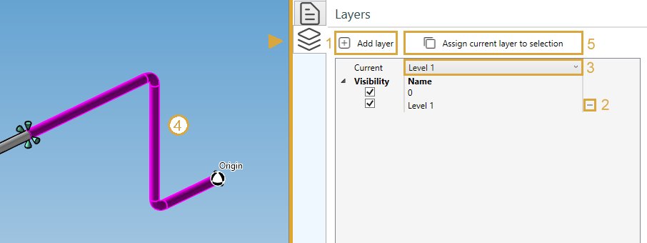
By default, all piping elements are assigned to Layer 0.
To create a new layer, click on Add layer button (1).
Give it a name, for example “Level 1”.
The layer “Level 1” will appear in the list of layers and will become the current layer (3).
To modify the layer of objects, select elements and/or restraints (4) and click on Assign current layer to selection button (5).
If you decide to remove a layer, click on - button (2) next to the layer name. All elements and restraints of this layer will be assigned to the default Layer 0.
You can now show/hide elements and restraints by activating/deactivating the visibility buttons.
All layer manipulations support Undo/Redo mechanism.