Model options
1. General

This tab lets you define the calculation code and its Edition, direction of gravity, input and output Units, Plant name and Engineer name.
ATTENTION, when starting a new project, be sure to select a specification that will be compatible with the Units, Code and Edition of the project and do not change these three properties during design.
2. Analysis

- Def. room T° : default room temperature (used to calculate thermal expansion)
- Def. oper. density and Def. test density : default operating and test density. These values can be superseded in Data for some cross sections or in the load case definition
- Def. design T° and Def. design P : default design temperature and pressure. For non-Class 1 piping codes, the allowable stress Sh is evaluated at the design temperature if the Hot allowable option is not checked
- Bend mesh angle : discretization angle for bends (in degrees). If 0, an angle of 0.05 rad is used by default. An angle of 15 degrees is generally considered as sufficient
- Mass modeling (for compatibility with PIPESTRESS only) :
- Lumped stat. and dyn. : lumped mass for static analysis, lumped mass for dynamic analysis
- Unif. stat. / Lumped dyn. : uniform mass for static analysis, lumped mass for dynamic analysis
- Lumped stat. / Lumped dyn. + rot. : lumped mass for static analysis, lumped mass and rotational inertia for dynamic analysis
- Unif. stat. / Lumped dyn. + rot. : uniform mass for static analysis, lumped mass and rotational inertia for dynamic analysis
- Branch modeling (non-Class 1 and non-B31J codes only) :
- Rigid : the imaginary element connecting the centerline with the surface of the run pipe is rigid
- Pipe : the imaginary element connecting the centerline with the surface of the run pipe is a pipe with the same cross section as the branch pipe
- Class 1 : the imaginary element connecting the centerline with the surface of the run pipe is modeled as in Class 1 codes (either rigid or rigid + element of negligible length with local flexibility)
- B31J : the imaginary element connecting the centerline with the surface of the run pipe is modeled as in B31J standard
- Hot modulus : for most non-Class 1 piping codes, the Young modulus Ec at room temperature is used by default for all load cases. If Hot modulus is checked, the Young modulus Eh at the operating temperature is used instead. For Class 1 piping codes, the Young modulus Eh at the operating temperature is always used
- Hot allowable : for non-Class 1 piping codes, the allowable stress at design temperature is used by default for all load cases. If Hot allowable is checked, the allowable at the operating temperature is used instead
- Pres. stiffening : check this option to take into account the pressure stiffening effect on elbows and miter bends (if permitted by the piping code)
- Pres. elongation : if PIPESTRESS solver is used and this option is checked, the elongation due to internal pressure (also called “Bourdon effect”) will be taken into account for all thermal expansion and test weight cases. If Code_Aster solver is used, this option has no effect, the option Include Bourdon effect in every load case definition is used instead
- PD/t pres. stress : the pressure stress is calculated with the formula Pd^2/(D0^2 - d^2) by default. The simpler formula PD/t is used if this option is checked
- Branch forces at surface : check this option to use the forces and moments at run surface instead of intersection point for tees (if permitted by the piping code)
- Thermal cycles per element : check this option to use the actual number of thermal cycles of every piping element, otherwise the maximum number of cycles is used for all piping elements
3. Class 1
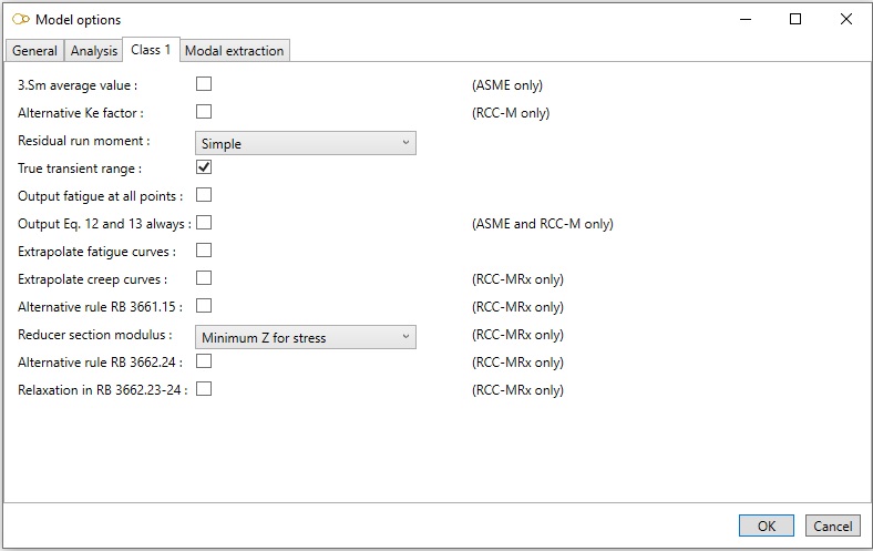
- 3.Sm average value : check this option to use the average value of 3Sm between two load sets instead of the minimum value (ASME only)
- Alternative Ke factor : if checked, the penalty factor Ke.therm is used for austenitic stainless steels and Ni-Cr-Fe alloys (RCC-M only)
- Residual run moment : determines how the residual run moments are calculated for unsigned cases. Contact CWANTIC for further explanations and theoretical background
- True transient range : by default, the range of the thermal gradient stress for a load set pair (LS1, LS2) is calculated assuming that the sign of the thermal stress is positive for heat-up transients and negative for cool-down transients. If this option is checked, the true range of the thermal gradient stress is calculated
- Output fatigue at all points : by default, the detailed results of the fatigue analysis are only output at points where the code limits are exceeded. If this option is checked, the detailed results are output at all points
- Output Eq. 12 and 13 always : by default, equations 12 and 13 are only output when equation 10 fails. If this option is checked, equations 12 and 13 are output in all cases (ASME and RCC-M only)
- Extrapolate fatigue curves : check this option to allow extrapolation of the fatigue curves
- Extrapolate creep curves : check this option to allow extrapolation of the creep curves from Appendix A3.52 and A3.53 (RCC-MRx only)
- Alternative rule RB 3661.15 : rule RB 3661.14 is used by default when the efficiency diagram is provided in Appendix A3.481. Check this option to use rule RB 3661.15 in all cases (RCC-MRx only)
- Reducer section modulus (RCC-MRx only) :
- Z of each end : the actual section modulus Z and ratio D/t of each end are used for stress check and calculation of elastic follow-up factors
- Minimum Z always : the minimum section modulus Z and maximum ratio D/t are used at both ends for stress check and calculation of elastic follow-up factors
- Minimum Z for stress : the minimum section modulus Z and maximum ratio D/t are used at both ends for stress check but the actual Z and D/t are used for calculation of elastic follow-up factors
- Alternative rule RB 3662.24 : if checked, rule RB 3662.24 is used instead of RB 3662.23 when the holding time is not located at one of the extrema of the cycle (RCC-MRx only)
- Relaxation in RB 3662.23-24 : if checked, relaxation is taken into account when applying rule RB 3662.23 or RB 3662.24 (RCC-MRx only)
4. Modal extraction

- Extract modes : check this option to extract the mode shapes
- Cut-off freq. : only the mode shapes below the cut-off frequency are extracted
- Max. number of modes : if cut-off frequency is 0, sets the number of modes to be extracted
- Auto. mesh freq. : if different from 0, additional mass points will be generated to ensure that the mode shapes up to this frequency are accurate. This frequency should be equal or larger than the cut-off frequency
- Ref. case : if the Hot modulus option is checked, the Young modulus Eh used for the modal extraction is evaluated at the temperature of the reference case
- Consistent masses : if checked, a consistent mass matrix is used
Other modal extractions (modal sets) may be added by clicking on button Add or removed by clicking on button Remove. For each additional modal extraction, the following parameters shall be entered :
- Name : identifier (may not be blank)
- Cut-off freq. : only the mode shapes below the cut-off frequency are extracted
- Max. number of modes : if cut-off frequency is 0, sets the number of modes to be extracted
- Ref. case : if the Hot modulus option is checked, the Young modulus Eh used for the modal extraction is evaluated at the temperature of the reference case